Physical quantity measuring apparatus and physical quantity measuring method

Inactive Publication Date: 2013-12-26
YOKOGAWA ELECTRIC CORP
View PDF3 Cites 0 Cited by
  • Summary
  • Abstract
  • Description
  • Claims
  • Application Information

AI Technical Summary

Benefits of technology

[0012]An object of the invention is to improve the accuracy of physical quantity measurement without inc

Problems solved by technology

However, since the input signal generally fluctuates out of sync with the operating clock signal, an error occurs between the measurement time T corresponding to the number L of periods of the input signal and a measurement result Ts.
However, when the high speed clock signal is used for measuring the measurement time T, the number of bits of a counter for counting the number of periods of the high speed clock signal increases to thereby cause the increase of the scale of the circuit.
When a measurement operation is perfor

Method used


Image

  • Physical quantity measuring apparatus and physical quantity measuring method
  • Physical quantity measuring apparatus and physical quantity measuring method
  • Physical quantity measuring apparatus and physical quantity measuring method

Examples


Example

[0026]An embodiment of the invention will be described with reference to the drawings. The embodiment will be described in the case where the invention is applied to a frequency measuring apparatus. However, the invention is not limited to the frequency measuring apparatus but may be applied to any general physical quantity measuring apparatus having a configuration in which a pulse interval between consecutive pulses belonging to an input signal is counted using an operating clock signal. Such a physical quantity measuring apparatus includes a pulse number count device, a pulse interval measuring device, etc.

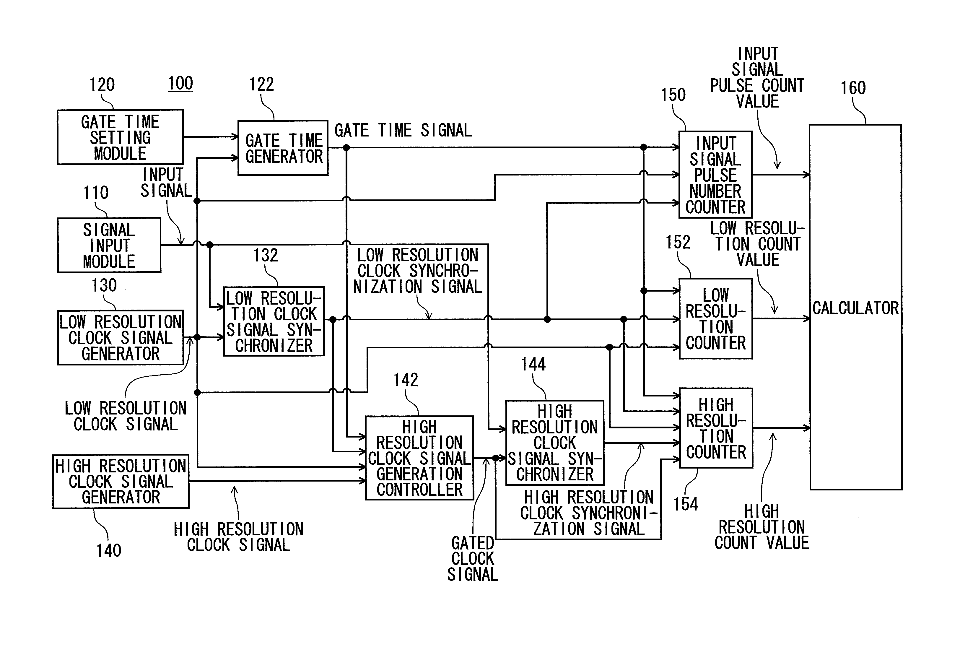
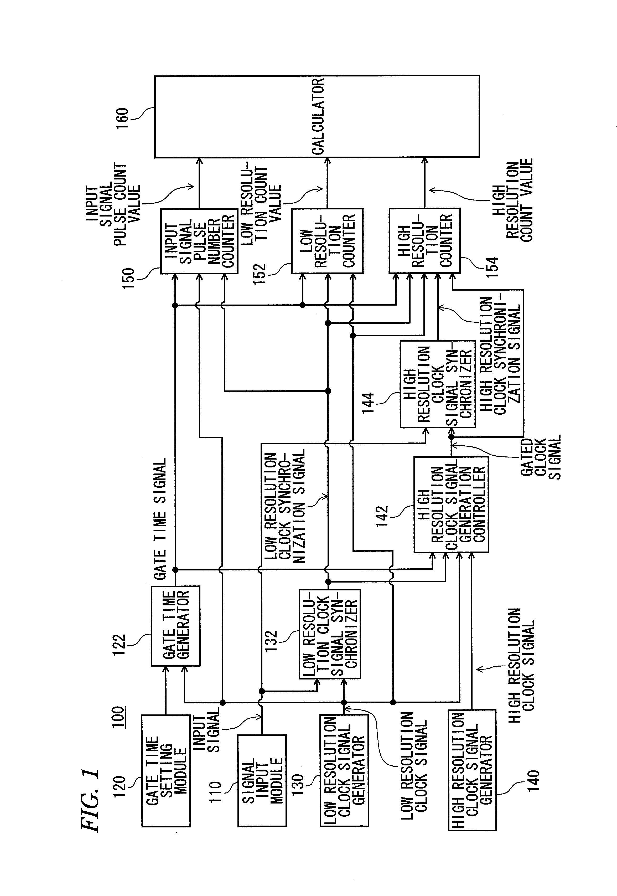
[0027]FIG. 1 is a block diagram showing a configuration of the frequency measuring apparatus according to the embodiment. As shown in FIG. 1, the frequency measuring apparatus 100 includes a signal input module 110, a gate time setting module 120, a gate time generator 122, a low resolution clock signal generator 130, a low resolution clock signal synchronizer 132, a high resol...


PUM


Abstract

A physical quantity measuring apparatus includes: a signal input module receiving an input signal having consecutive pulses; a low resolution clock signal generator generating a low resolution clock signal; a high resolution clock signal generator generating a high resolution clock signal; a gate time generator outputting gate time signals at a predetermined interval; a low resolution clock signal synchronizer generating a low resolution clock synchronization signal; a low resolution counter counting the number of rising edges of the low resolution clock signal; a high resolution clock signal generation controller outputting the high resolution clock signal as a gated clock signal; a high resolution clock signal synchronizer generating a high resolution clock synchronization signal; and a high resolution counter counting the number of rising edges of the gated clock signal.

Description

CROSS-REFERENCE TO RELATED APPLICATION[0001]This application claims priority from Japanese Patent Applications No. 2012-138887, filed on Jun. 20, 2012, the entire contents of which are herein incorporated by reference.BACKGROUND[0002]1. Technical Field[0003]The present disclosure relates to a pulse number counting technique in which an interval between consecutive pulses belonging to an input signal is counted using a clock signal to thereby measure a physical quantity such as the frequency or the pulse interval of the input signal.[0004]2. Related Art[0005]When the frequency of an input signal of consecutive pulses is measured, the number L of periods of the input signal occurring within a measurement time T can be counted and L / T [Hz] can be calculated to obtain the frequency, as shown in FIG. 9.[0006]In real measurement using a digital measuring instrument operating in accordance with a predetermined clock, an input signal is sampled using the operating clock signal within the me...

Claims


Application Information

Patent Timeline
IPC IPC(8): G04F10/04
CPCG04F10/04G01R23/10G01R29/02
Inventor SASAKI, SHINICHI
Owner YOKOGAWA ELECTRIC CORP
Why Eureka
Try Eureka