Insulation deterioration detection apparatus

a detection apparatus and insulation resistance technology, applied in the direction of instruments, angiography, battery/fuel cell control arrangement, etc., can solve the problems of increased cost, increased complexity of filter circuit configuration, and inability to accurately detect the insulation resistance between the vehicle body and the high-voltage circuit, so as to reduce the insulation resistance and remove the effect of noise and a higher signal-to-noise ratio

Active Publication Date: 2014-01-02
DENSO CORP
View PDF3 Cites 6 Cited by
  • Summary
  • Abstract
  • Description
  • Claims
  • Application Information

AI Technical Summary

Benefits of technology

[0011]In accordance with an exemplary embodiment of the present invention, there is provided an apparatus for detecting reduction in insulation resistance between a vehicle body and a high-voltage circuit. In the apparatus, a coupling capacitor is electrically connected to the high-voltage circuit at a predefined point of the high-voltage circuit via a first terminal of the coupling capacitor. An oscillation circuit is configured to apply an AC voltage of a predetermined frequency to a second terminal of the coupling capacitor through a predetermined output impedance. A determiner is configured to determine reduction in insulation resistance between the vehicle body and the high-voltage circuit on the basis of a change in potential to ground at the second terminal of the coupling capacitor. A digital filter is configured to remove noise included in the potential to ground to be forwarded to the determiner, where the digital filter is electrically connected between the second terminal of the coupling capacitor and a signal input of the determiner. An aliasing suppression circuit is configured to suppress aliasing in the digital filter, where the aliasing suppression circuit is electrically connected between the second terminal of the coupling capacitor and a signal input of the digital filter, and the aliasing suppression circuit includes a resistor electrically connected to the second terminal of the coupling capacitor. A protection circuit is configured to protect the determiner and the digital filter from high-voltage noise generated in the high-voltage circuit, where the protection circuit is electrically disposed between the resistor of the aliasing suppression circuit and the signal input of the digital filter.
[0012]With this configuration, the filter for removing noise included in the potential to ground at the second terminal of the coupling capacitor includes the digital filter having a higher signal to noise ratio than an analog filter, and the aliasing suppression circuit for suppressing aliasing in the digital filter. This allows the determiner to more accurately detect the potential to ground at the second terminal of the coupling capacitor.
[0013]In addition, the protection circuit is electrically disposed between the resistor of the aliasing suppression circuit and the signal input of the digital filter, where a potential at a junction between the resistor of the aliasing suppression circuit and the signal input of the digital filter is lower than a potential at the second terminal of the coupling capacitor upon application of the high-voltage noise to the apparatus. This can ensure high voltage resistance without using high voltage-resistance elements or the like for the protection circuit.
[0014]This leads to a higher accuracy of detecting reduction in insulation resistance between the high-voltage circuit and the vehicle body while ensuring high voltage resistance of the apparatus with a simpler configuration.

Problems solved by technology

However, since various properties of the analog filter may alter due to, for example, a temperature variation and aging degradation and the like of each of elements constituting the analog filter, the accuracy of detecting insulation resistance between the vehicle body and the high-voltage circuit is inevitably low.
This however may lead to a more complicated configuration of the filter circuit and thus to increased cost.
This may lead to further increased cost.

Method used


Image

  • Insulation deterioration detection apparatus
  • Insulation deterioration detection apparatus
  • Insulation deterioration detection apparatus

Examples


first embodiment

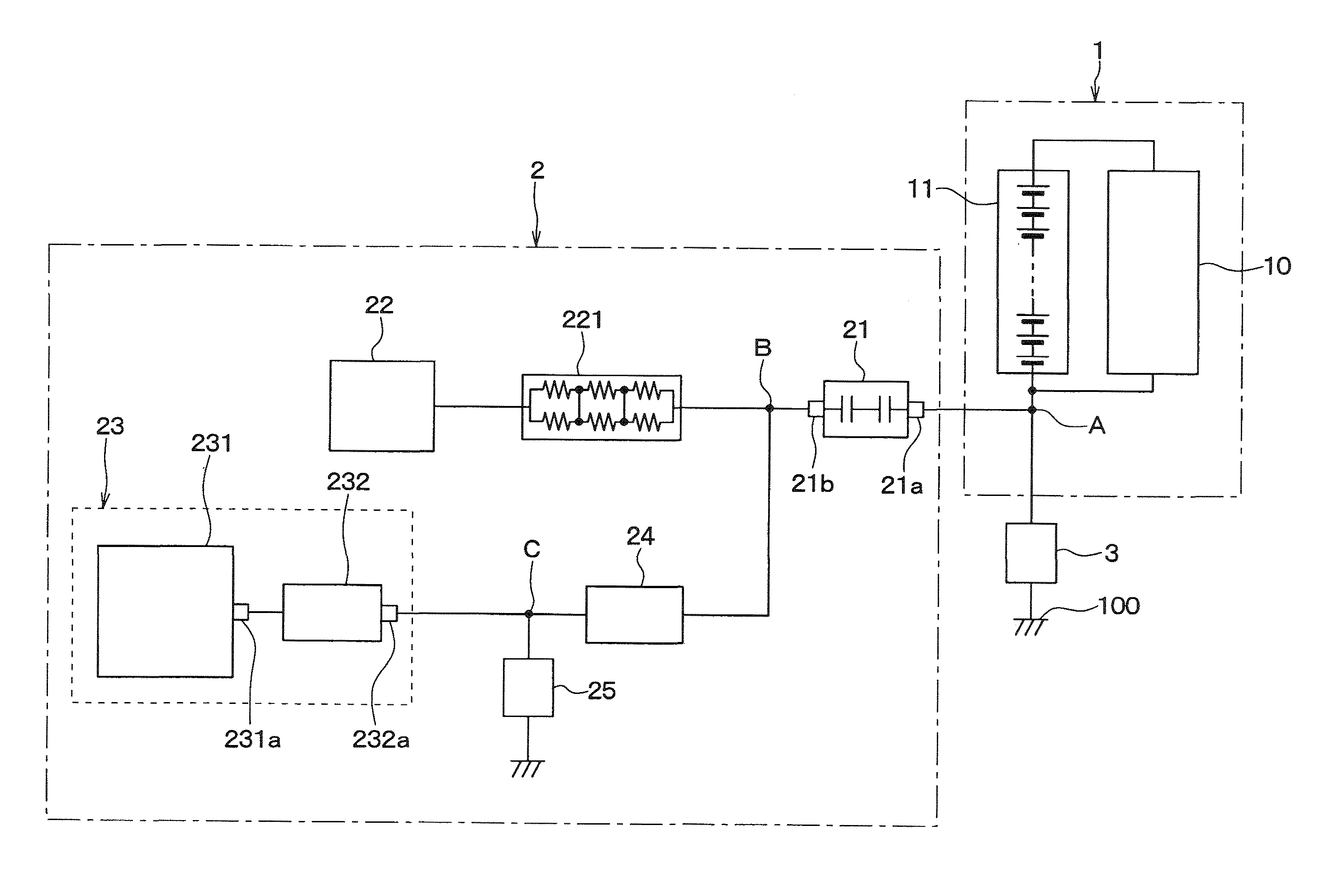
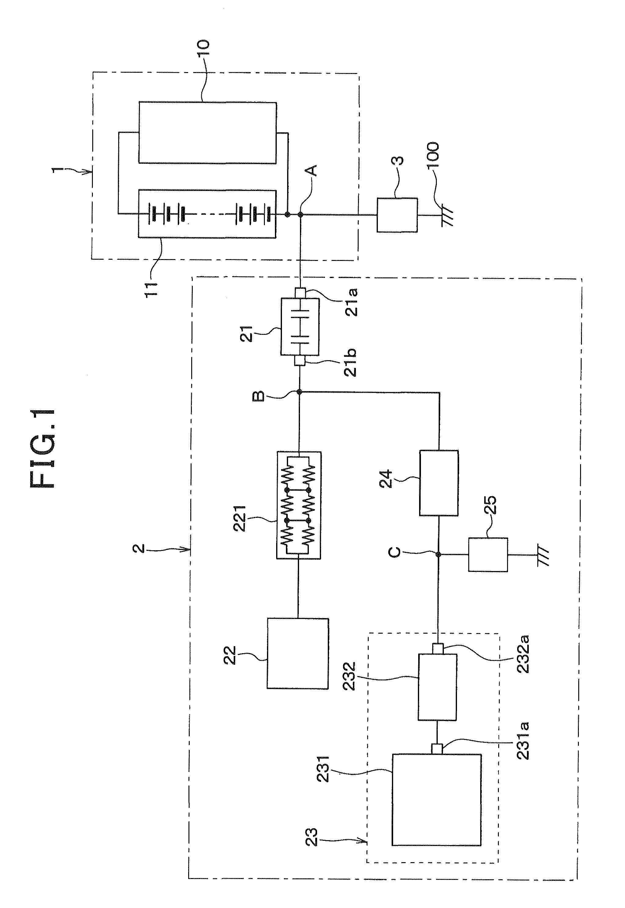
[0031]There will now be explained a first embodiment of the present invention. An insulation deterioration detection apparatus 2 of the present embodiment is configured to detect reduction in insulation resistance between a vehicle body 100 and a high-voltage circuit 1 mounted in the vehicle, and is applicable to a vehicle equipped with a high-voltage battery 11, such as a hybrid vehicle or an electrical vehicle.

[0032]The high-voltage circuit 1 includes various electrical loads 10, such as a vehicle prime mover and the like, and a high-voltage battery 11 that supplies electrical power to the electrical loads 10. The high-voltage battery 11 is a high-voltage power supply (e.g., of 300V) including an assembled battery, such as a series connection of a plurality of lithium-ion batteries or the like.

[0033]Basically, the high-voltage battery 11 of the high-voltage circuit 1 is electrically isolated from the vehicle body 100. However, there actually exists, for example, a ground insulatio...

second embodiment

[0059]There will now be explained a second embodiment of the present invention. Elements of the present embodiment similar or equivalent to those described in the first embodiment will not be explained or will be explained in a simplified manner.

[0060]In the present embodiment, as shown in a circuit diagram of FIG. 9, the protection circuit 25 includes a grounding capacitor 251 and a voltage limiter circuit 252 formed of clamping diodes 252a, 252b.

[0061]The voltage limiter circuit 252 is electrically disposed between the grounding capacitor 251 and the signal input 232a of the digital filter 232, and limits a voltage to be inputted to the digital filter 232.

[0062]In the present embodiment, the protection circuit 25 additionally includes the voltage limiter circuit 252. This leads to more secure protection of the determiner 231 and the digital filter 232 of the control circuit 23 from the high-voltage noise generated in the high-voltage circuit 1.

[0063]Alternatively, the voltage lim...

third embodiment

[0064]There will now be explained a third embodiment of the present invention. Elements of the present embodiment similar or equivalent to those described in any one of the first and second embodiments will not be explained or will be explained in a simplified manner.

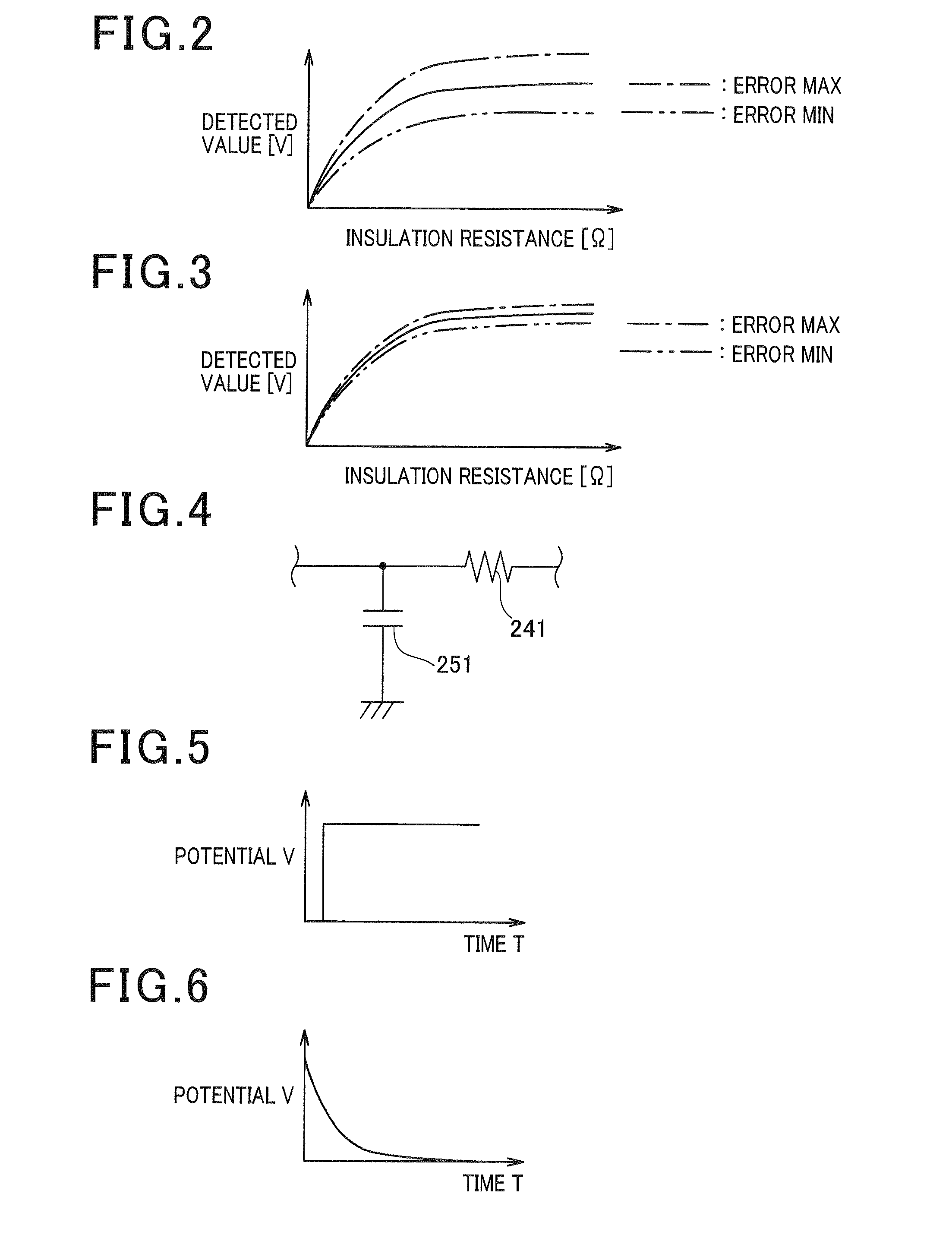
[0065]The present embodiment is similar to each of the first and second embodiments except that, as shown in FIG. 11, the aliasing suppression circuit 24 includes, in addition to the resistor 241 and the grounding capacitor 251, an amplifier circuit 242 as an active filter. The amplifier circuit 242 includes an operational amplifier 242a as an active element, resistors 242b-242d and a capacitor 242e as passive elements. In the present embodiment, the protection circuit 25 is electrically disposed between the resistor 241 of the aliasing suppression circuit 24 electrically connected to the second terminal 21b of the coupling capacitor 21, and the amplifier circuit 242.

[0066]The present embodiment provides similar benefit...


PUM


Abstract

An apparatus capable of detecting reduction in insulation resistance between a vehicle body and a high-voltage circuit. In the apparatus, a filter for removing noise included in a potential to ground at a terminal of a coupling capacitor includes a digital filter and an aliasing suppression circuit for suppressing aliasing in the digital filter. In addition, a protection circuit, which protects the digital filter and a determiner operable to detect the reduction in insulation resistance from high-voltage noise generated in the high-voltage circuit, is electrically disposed between a resistor of the aliasing suppression circuit and a signal input of the digital filter, where a potential at a junction between the resistor of the aliasing suppression circuit and the signal input of the digital filter is lower than a potential at the terminal of the coupling capacitor upon application of the high-voltage noise to the apparatus.

Description

CROSS-REFERENCE TO RELATED APPLICATION[0001]This application is based on and claims the benefit of priority from earlier Japanese Patent Application No. 2012-148594 filed Jul. 2, 2012, the description of which is incorporated herein by reference.BACKGROUND[0002]1. Technical Field[0003]The present invention relates to an apparatus configured to detect reduction in insulation resistance between a vehicle body and a high-voltage circuit.[0004]2. Related Art[0005]A formerly known vehicle including a high-voltage battery system including a high-voltage circuit, such as a hybrid vehicle or an electrical vehicle, is equipped with an apparatus which detects reduction in insulation resistance between a vehicle body and the high-voltage circuit, for ensuring safety of occupants or the like (see, for example, Japanese Patent No. 3781289).[0006]The apparatus disclosed in Japanese Patent No. 3781289 adopts a technique for detecting insulation deterioration between the vehicle body and the high-v...

Claims


Application Information

Patent Timeline
Patent Type & Authority Applications(United States)
IPC IPC(8): G01R31/02
CPCG01R31/025G01R1/36G01R27/18G01R31/006B60L3/0069B60L3/12B60L2270/147B60L58/21G01R31/52Y02T10/70A61B5/021G01L9/0041
Inventor MIZOGUCHI, HAYATOMAEBARA, TSUNEO
Owner DENSO CORP
Why Eureka
Try Eureka