
Surface-stabilized ips LCD

Active Publication Date: 2014-01-02
KENT STATE UNIV
View PDF3 Cites 10 Cited by
  • Summary
  • Abstract
  • Description
  • Claims
  • Application Information

AI Technical Summary

Benefits of technology

This patent describes a method for making a special type of LCD screen that switches quickly. The method involves using a special material called polymer fibrils that align the liquid crystals in the screen when there is no electricity applied. This allows for better control over the movement of the liquid crystals and results in a more dynamic and beautiful display. The invention also includes a method for making the alignment layers that control the movement of the liquid crystals in the screen. Overall, this patent describes a way to make LCD screens that are faster, smarter, and more visually appealing.

Problems solved by technology

Finally, because IPS-Pro based LCDs are highly complex, they are expensive to produce, and as such, they are used only in applications where image clarity and precision is considered critical, such as in the medical field, including surgical applications, as well as in advanced engineering and science applications.
However, due to the slow decay time, current IPS LCDs are unable to display moving images with high quality.

Method used


Image

  • Surface-stabilized ips LCD
  • Surface-stabilized ips LCD
  • Surface-stabilized ips LCD

Examples


example 1

[0035]Specifically, the following example presents the testing results of the SS-IPS LCD cell 10 when placed between polarizers that are crossed at 90 degrees with respect to each other, whereby one polarizer is aligned with the average orientation of the nematic LC molecules that is the optical axis in the field-off state. When no electric field is applied, the SS-IPS LCD cell 10 that was placed between the crossed polarizers was viewed as dark. When an AC voltage (square wave) of 1 kHz was applied across the electrodes 40,50, the SS-IPS LCD cell 10 experienced an increase in light transmission and reached a maximum light transmittance at an applied voltage.

[0036]Continuing, FIG. 6 shows a plot or graph of the light transmittance as a function of applied voltage for both a standard IPS LCD cell with an LC mixture with 0% polymer (curve 100) and the SS-IPS LCD cell 10 of the present invention with the LC mixture 80 having a 0.2% (curve 110), 1% (curve 120), and 3% (curve 130) polyme...

example 2

[0039]In a second example, the SS-IPS LCD cell 10 of the present invention was constructed in the same manner as in example 1, with the exception that a voltage of 7VDC was applied to the cell 10 during the photopolymerization of the monomer of the LC material 80.

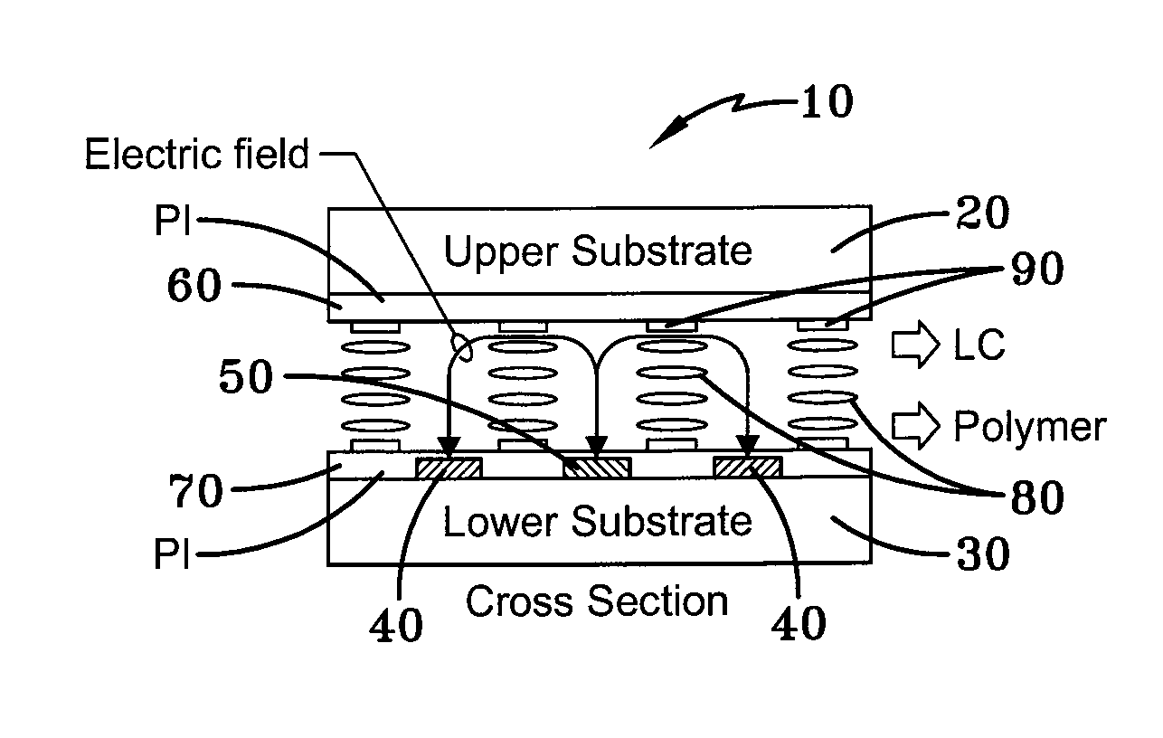
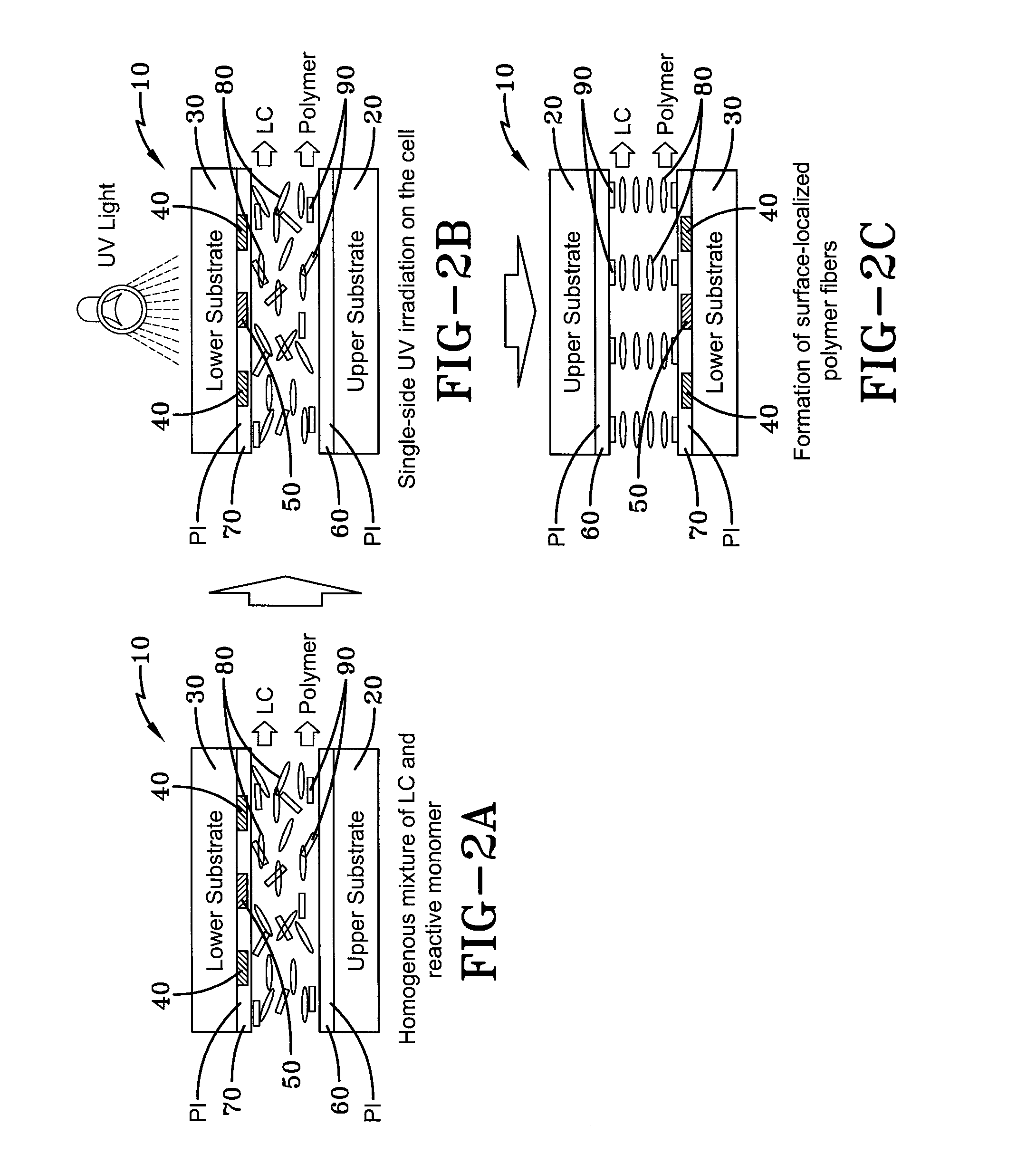
[0040]With a surface-localized polymer or polymer islands 90, the surface-anchoring characteristics of the liquid crystal molecules can be changed, depending on the density of the polymer islands 90. Morphological studies of the SS-IPS LCD cell 10 were carried out using a scanning electron microscope (SEM) in order to show that different electro-optical properties of the SS-IPS LCD cells 10 are caused by the polymer islands 90 or by structures formed at the surfaces of the samples. The results of the SEM analysis are shown in FIGS. 9a-c, whereby the Figs. show the SEM analysis of a 3% polymer SS-IPS LC cell 10 having polymer islands 90 that are grown on both surfaces of the substrates 20,30 with a preferential orientation d...


PUM


Abstract

A surface-stabilized in-plane switching (SS-IPS) liquid crystal (LCD) cell includes a pair of spaced substrates that include alignment layers disposed thereon. The alignment layers are treated to define a first director orientation. Disposed between the alignment layers is a liquid crystal material that contains polymer fibrils that are disposed upon each of the alignment layers. The polymer fibrils serve to maintain the alignment of the liquid crystal molecules in the first director orientation when no voltage is applied to the LCD cell via interdigitated electrodes disposed upon the alignment layers, thus improving the dynamic response of the SS-IPS LCD cell.

Description

CROSS-REFERENCE TO RELATED APPLICATION[0001]This application claims the benefit of U.S. Provisional Application No. 61 / 664,808 filed on Jun. 27, 2012, the contents of which are incorporated herein by reference.TECHNICAL FIELD[0002]The present invention relates to liquid crystal display (LCD) devices. In particular, the present invention relates to an in-plane switching (IPS) LCD. More particularly, the present invention relates to surface-stabilized IPS LCDs that utilize low-density surface-localized polymer islands to improve its dynamic response.BACKGROUND OF THE INVENTION[0003]In-plane switching (IPS) is a leading liquid crystal display (LCD) technology, which has as one of its main features the ability to align liquid crystals horizontally to increase their viewing angle while allowing the transmittance of the LCD to be changed. Due to this, IPS technology was unanimously adopted at its introduction by the LCD industry and was one of the first refinements to LCDs, to be incorpor...

Claims


Application Information

Patent Timeline
IPC IPC(8): G02F1/1337
CPCG02F1/133703G02F1/133788G02F1/134363G02F2202/022G02F2202/36
Inventor CHIEN, LIANG-CHYHWANG, JEOUNG-YEON
Owner KENT STATE UNIV
Features
  • Generate Ideas
  • Intellectual Property
  • Life Sciences
  • Materials
  • Tech Scout
  • Unparalleled Data Quality
  • Higher Quality Content
  • 60% Fewer Hallucinations
Learn More