
Catheter comprising capacitive micromachined ultrasonic transducers with an adjustable focus

a micromachined ultrasonic transducer and adjustable focus technology, which is applied in the field of catheters, can solve the problems of difficult ablation of the entire prostate gland, difficult protection of non-targeted tissues such as the urethra and rectal wall, and inflexible conventional piezo crystals, etc., and achieves a wide angular range. , the effect of easy insertion into the subject and higher power ra

Active Publication Date: 2014-01-02
KONINKLIJKE PHILIPS ELECTRONICS NV
View PDF31 Cites 79 Cited by
  • Summary
  • Abstract
  • Description
  • Claims
  • Application Information

AI Technical Summary

Benefits of technology

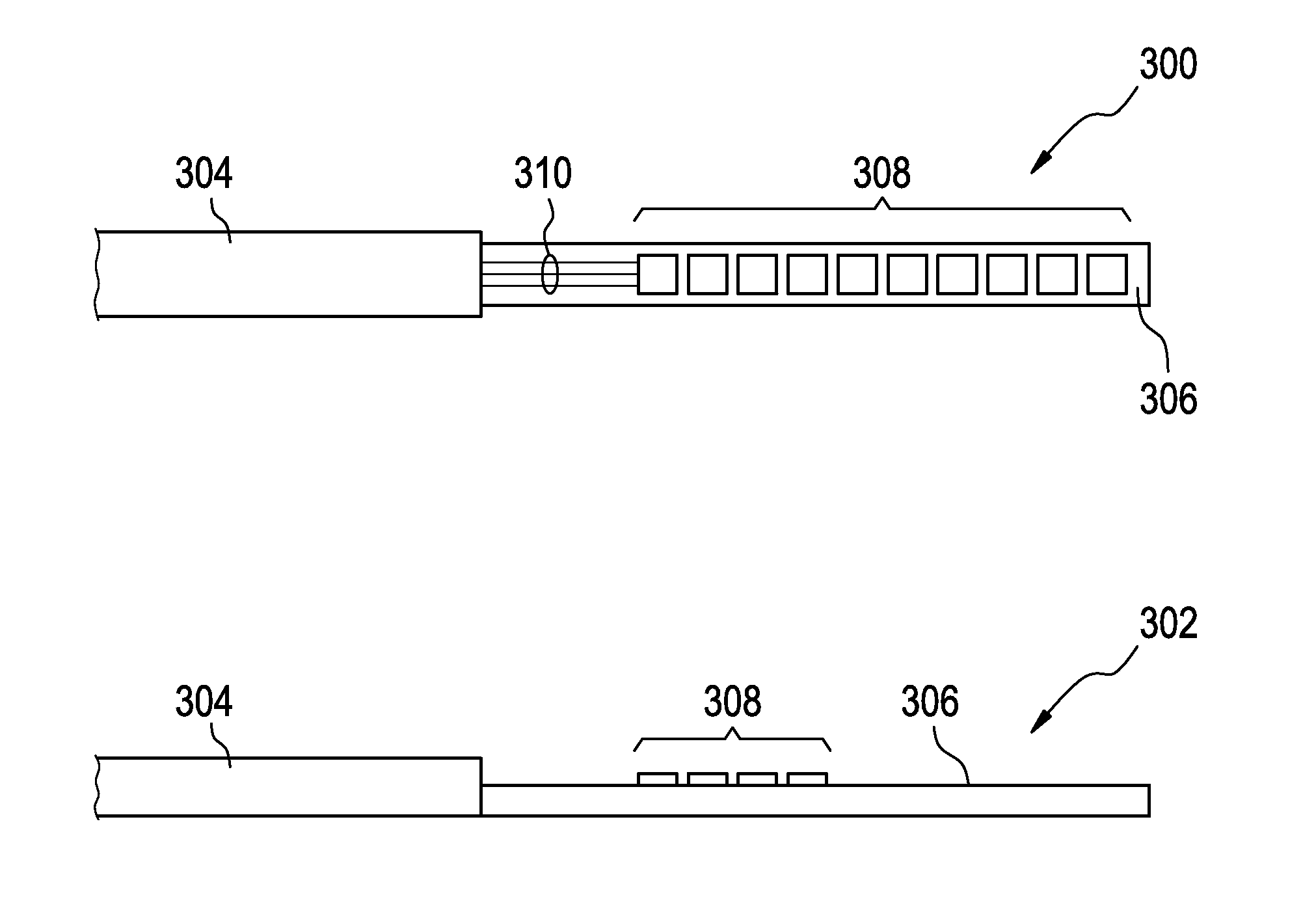
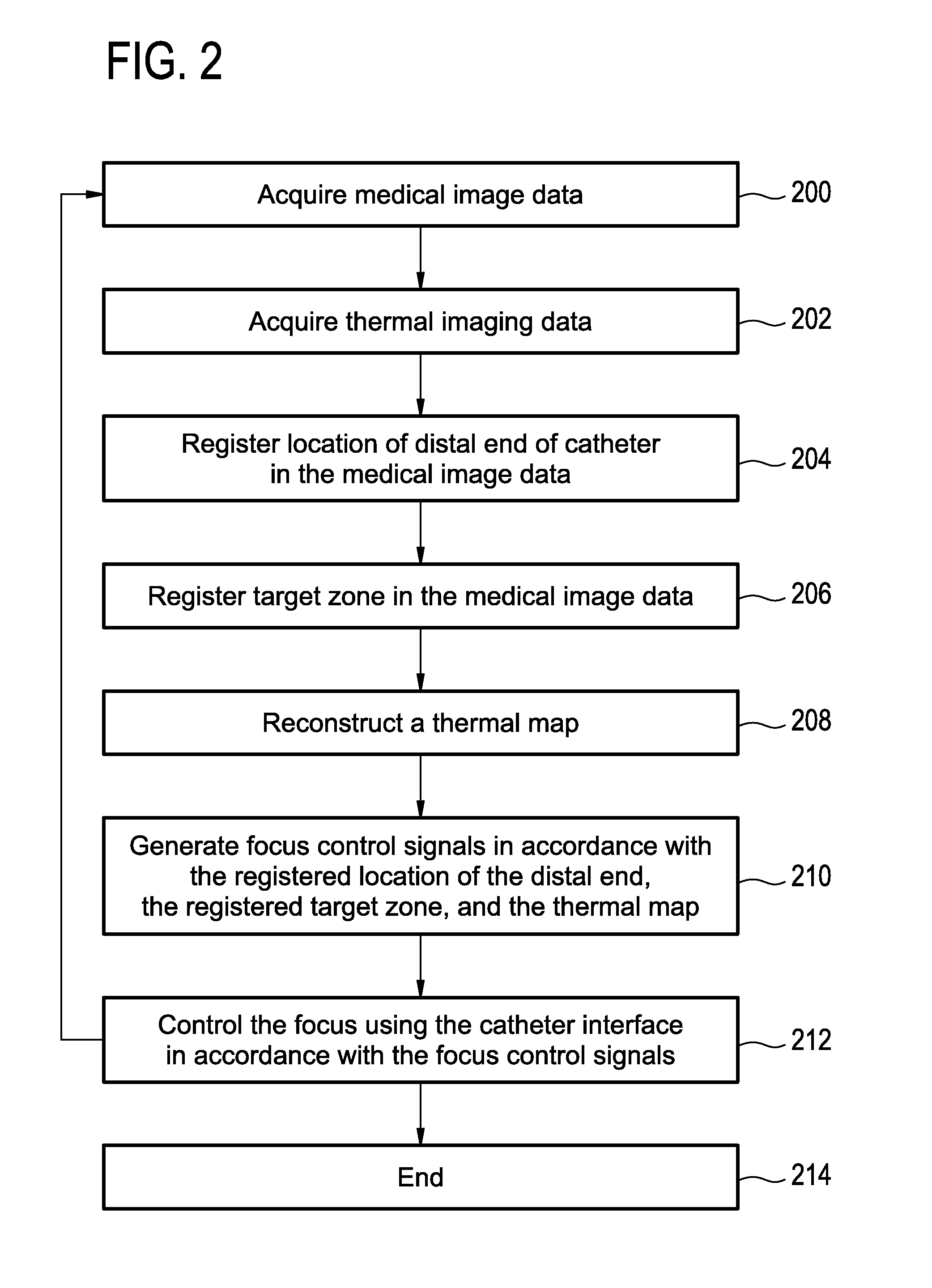
The patent describes a method of using capacitive micromachined ultrasound transducers (CMUTs) for transurethral HIFU ablation procedures. CMUTs offer advantages such as smaller size and lower cost compared to traditional piezoceramic or piezocomposite transducers. They also allow for a two-dimensional phased array that can focus on the target area, increasing accuracy and safety. However, the number of elements perpendicular to the catheter is low, resulting in a relative broad focus in one direction. To improve the resolution in X and Y, a higher number of elements perpendicular to the catheter can be used, but this raises the cost and makes the transducers non-disposable. In this embodiment, the processor registers a target area in the subject using medical image data and generates focus control signals to control the focus of the CMUTs on the target area. This improves the accuracy and minimizes the risk of injury during the treatment.

Problems solved by technology

However, the number of elements perpendicular to the catheter is low, which results in a relative broad focus in that direction.
In addition, silicon transducers can be made flexible, however conventional piezo crystals are not flexible.
However, ablation of the entire prostate gland is difficult (especially anterior wall), and the protection of non-targeted tissues such as the urethra and rectal wall are also challenging.

Method used


Image

  • Catheter comprising capacitive micromachined ultrasonic transducers with an adjustable focus
  • Catheter comprising capacitive micromachined ultrasonic transducers with an adjustable focus
  • Catheter comprising capacitive micromachined ultrasonic transducers with an adjustable focus

Examples


Embodiment Construction

[0120]Like numbered elements in these figures are either equivalent elements or perform the same function. Elements which have been discussed previously will not necessarily be discussed in later figures if the function is equivalent.

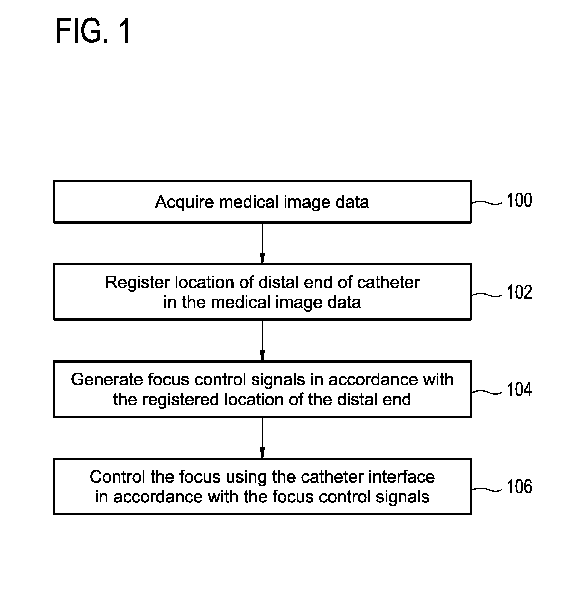
[0121]FIG. 1 shows a flow diagram which illustrates a method according to an embodiment of the invention. In step 100 medical image data is acquired. In step 102 a location of a distal end of the catheter is registered in the medical image data. The distal end of the catheter may be recognized using image recognition techniques. For instance a portion of the catheter may be identified outside of the subject and the catheter may have a particular appearance in the particular medical imaging modality. For instance the catheter may be made of a material which has particularly large or low contrast in a particular imaging modality. The catheter may also have a shape or contain a region which is easily identifiable in the medical image data. Step 102 may als...


PUM


Abstract

A catheter (700, 800, 1206) comprising: a shaft with distal (808, 906, 1004, 208) and proximal ends (1006),wherein the distal end comprises at least one array of capacitive micromachined ultrasound transducers (308, 402, 404, 500, 512, 600, 604,802, 008) with an adjustable focus for controllably heating a target zone (806, 1014, 1210); and a connector (1012) at the proximal end for supplying the at least one array of capacitive micromachined ultrasound transducers with electrical power and for controlling the adjustable focus.

Description

TECHNICAL FIELD[0001]The invention relates to catheters for heating a target volume of a subject with ultrasonic energy, in particular the invention relates to the use of capacitive micromachined ultrasonic transducers for generating the ultrasound and the use of medical imaging for controlling the focus of the generated ultrasound.BACKGROUND OF THE INVENTION[0002]High-intensity focused ultrasound (HIFU) ablation of the prostate has conventionally been done through the rectal wall with a transrectal probe. Alternatively, ablation can also be done through the wall of the urethra using a transurethral probe. The transurethral approach has several safety-related advantages as compared to the transrectal approach. Because the location of the urethra is known (probe within urethra), it is easier to avoid unintentional thermal damage to the urethra that might increase the risk of incontinency. Moreover, since there is no sonication through the rectal wall, the risk of damaging this sensit...

Claims


Application Information

Patent Timeline
IPC IPC(8): A61N7/02A61B5/055A61B5/01A61B6/00A61B8/12A61B8/00A61B5/00A61B6/03
CPCA61N7/022A61B5/4836A61B5/055A61B6/03A61B6/4057A61B8/12A61B8/54A61B5/015A61B5/064A61B6/12A61B8/0841A61B8/445A61B8/4488A61B8/58A61B2018/00023A61B2562/028A61N2007/0095A61B2090/064A61B2090/374A61B5/0036B06B1/0292
Inventor KOHLER, MAX OSKARDIRKSEN, PETERSOKKA, SHUNMUGAVELUDEKKER, RONALD
Owner KONINKLIJKE PHILIPS ELECTRONICS NV
Learn More