Pulsed level gauge system with temperature-based control of pulse repetition frequency

a level gauge and pulse repetition technology, applied in the direction of volume measurement, volume measurement apparatus/methods, reradiation, etc., can solve the problems of time needed, relatively complicated, cumbersome, etc., and achieve the effect of energy efficien

Active Publication Date: 2014-01-02
ROSEMOUNT TANK RADAR
View PDF7 Cites 9 Cited by
  • Summary
  • Abstract
  • Description
  • Claims
  • Application Information

AI Technical Summary

Benefits of technology

[0014]In view of the above, a general object of the present invention is to provide an improved pulsed radar level gauge system and method, and in particular a pulsed radar level gauge system and method enabling a more energy efficient filling level determination.

Problems solved by technology

The method according to U.S. Pat. No. 7,412,337, however, appears relatively complicated and cumbersome, and there also appears to be room for further improvement in respect of reducing the time needed for the control.

Method used


Image

  • Pulsed level gauge system with temperature-based control of pulse repetition frequency
  • Pulsed level gauge system with temperature-based control of pulse repetition frequency
  • Pulsed level gauge system with temperature-based control of pulse repetition frequency

Examples


Embodiment Construction

[0050]In the present detailed description, various embodiments of the level gauge system according to the present invention are mainly discussed with reference to a pulsed radar level gauge system of the non-contact type, in which an electromagnetic signal is propagated towards the product contained in the tank using a propagation device in the form of a radiating antenna, such as a cone antenna, a horn antenna, an array antenna or a patch antenna.

[0051]It should be noted that this by no means limits the scope of the present invention, which is equally applicable to a pulsed guided wave radar (GWR) level gauge system utilizing a propagation device in the form of a transmission line probe, such as a single line probe (including a so-called Goubau probe), a two-lead probe, a coaxial probe, etc.

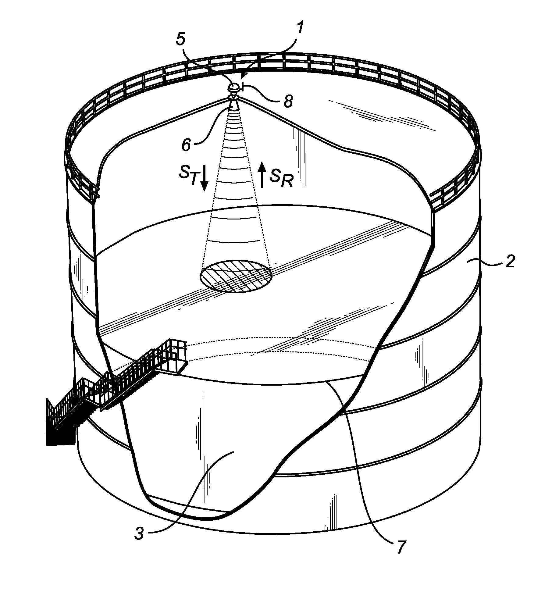
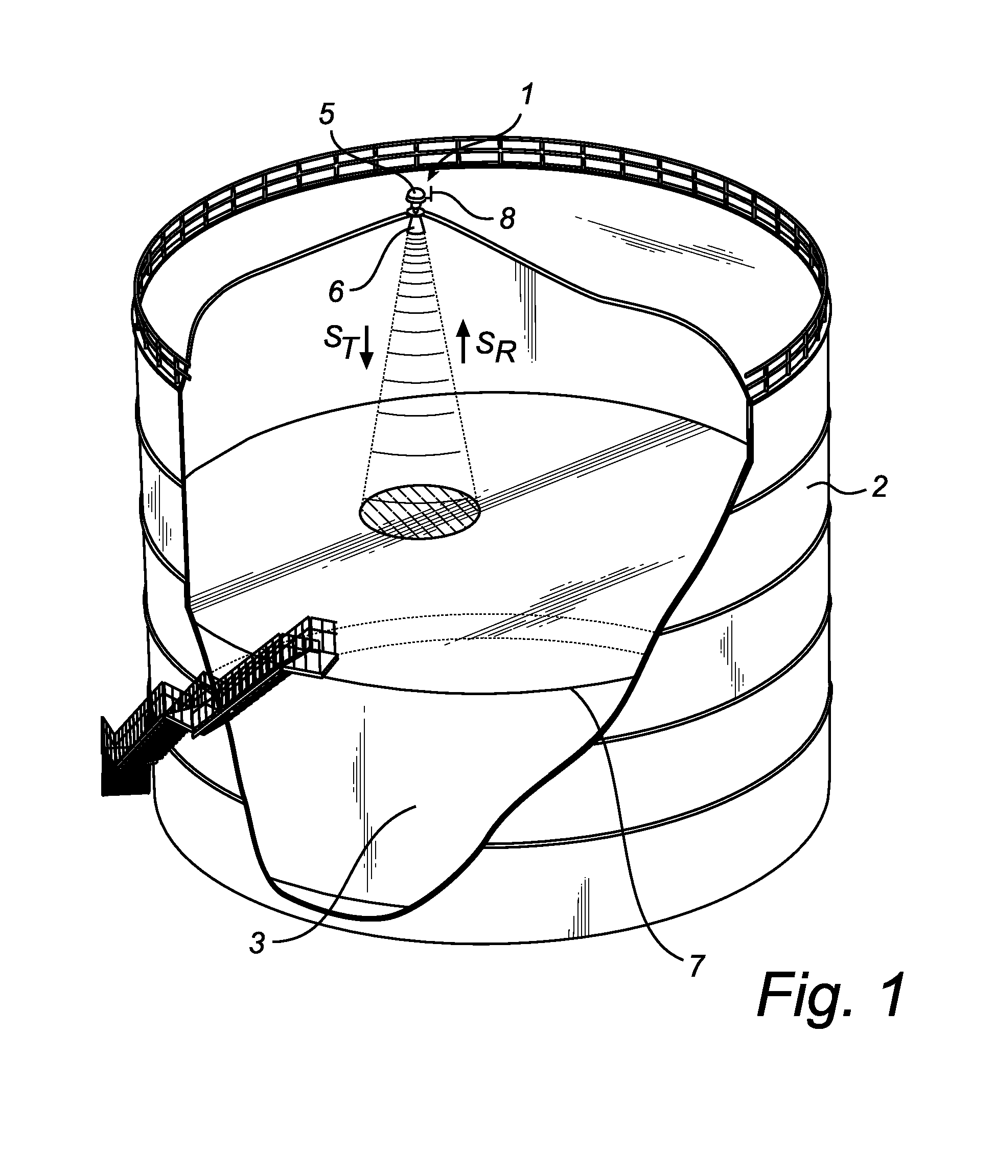
[0052]FIG. 1 schematically illustrates a level gauge system 1 arranged on top of a tank 2 for determining the filling level of a product 3 contained in the tank 2 using microwaves. The level gau...


PUM


Abstract

The present invention relates to a method of controlling a pulsed radar level gauge system, comprising the steps of: acquiring a signal indicative of a present operating temperature; determining an initial frequency control parameter for control of at least one of transmission signal generating circuitry and reference signal generating circuitry based on the present operating temperature and a plurality of data sets each comprising data indicative of a previous operating temperature and a previously determined frequency control parameter for the previous operating temperature; and controlling, starting from the initial frequency control parameter, at least one of the transmission signal generating circuitry and the reference signal generating circuitry to achieve the known frequency difference between the first pulse repetition frequency and the second pulse repetition frequency at the present operating temperature.

Description

FIELD OF THE INVENTION[0001]The present invention relates to a pulsed level gauge system and to a method of controlling such a pulsed level gauge system.TECHNICAL BACKGROUND[0002]Radar level gauge (RLG) systems are in wide use for determining the filling level of a product contained in a tank. Radar level gauging is generally performed either by means of non-contact measurement, whereby electromagnetic signals are radiated towards the product contained in the tank, or by means of contact measurement, often referred to as guided wave radar (GWR), whereby electromagnetic signals are guided towards and into the product by a probe acting as a waveguide. The probe is generally arranged to extend vertically from the top towards the bottom of the tank. The probe may also be arranged in a measurement tube, a so-called chamber, that is connected to the outer wall of the tank and is in fluid connection with the inside of the tank.[0003]The transmitted electromagnetic signals are reflected at ...

Claims


Application Information

Patent Timeline
Patent Type & Authority Applications(United States)
IPC IPC(8): G06F19/00
CPCG01S7/4008G01S13/88
Inventor NILSSON, LEIFDELIN, HAKANNYBERG, HAKAN
Owner ROSEMOUNT TANK RADAR
Why Eureka
Try Eureka