Status monitoring system and status monitoring method for rolling device

Inactive Publication Date: 2014-01-09
NTN CORP
View PDF17 Cites 53 Cited by
  • Summary
  • Abstract
  • Description
  • Claims
  • Application Information

AI Technical Summary

Benefits of technology

[0019]As discussed above, it may be said that when water admixes into the lubricant for use with rolling component part parts that is used under the condition involving the sliding motion, hydrogen is more generated and is apt to intrude into the steel material. The rolling component part parts appear to have a tendency of being increasingly used in the future under the condition sus

Problems solved by technology

In addition, the patent document 2 is only limited to the diagnosis of

Method used


Image

  • Status monitoring system and status monitoring method for rolling device
  • Status monitoring system and status monitoring method for rolling device
  • Status monitoring system and status monitoring method for rolling device

Examples


Example

Specific Example 1

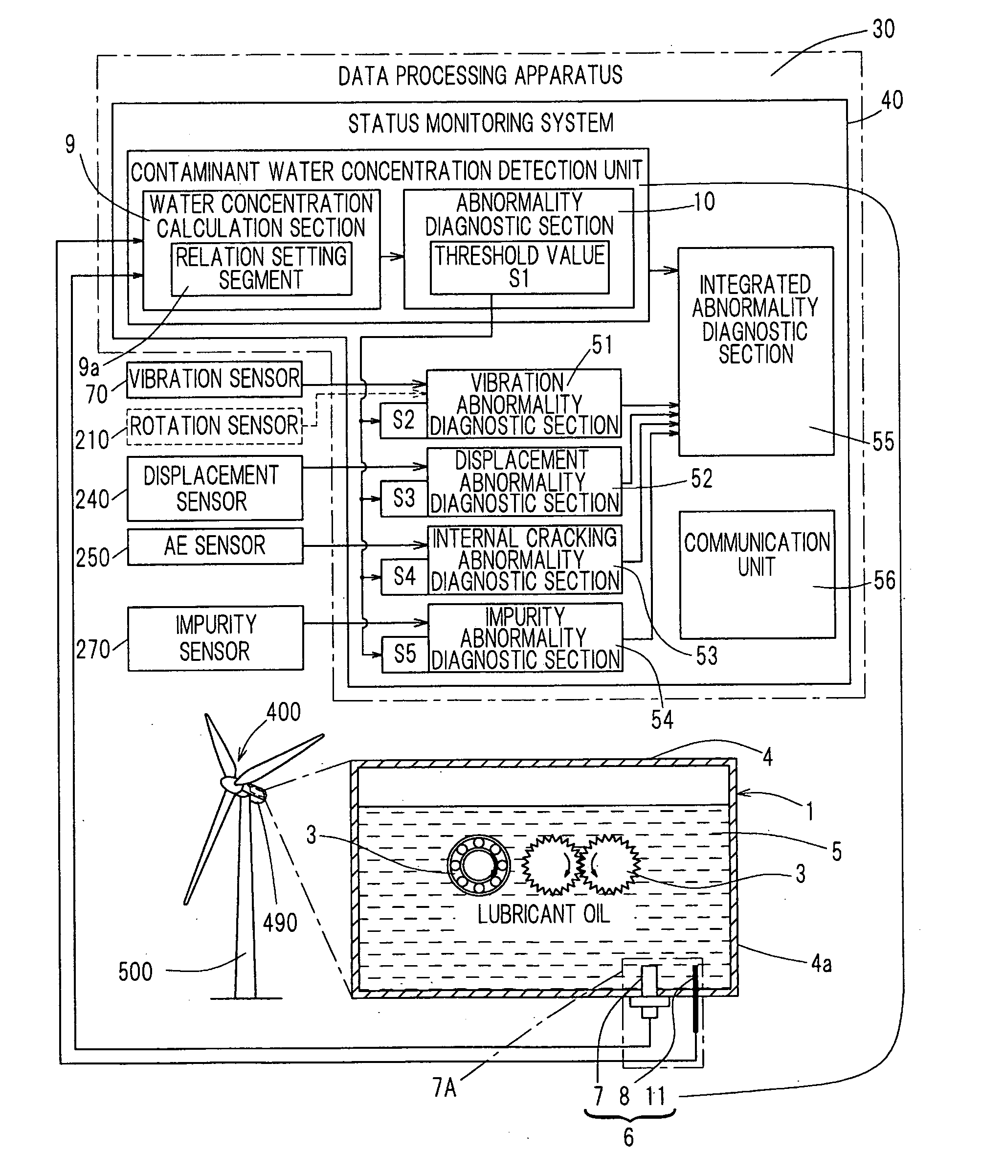
[0228]Referring to FIG. 29, the vibration sensor 70 is installed in a bearing forming the rolling device 1 shown in FIG. 20, for example, the main shaft bearing 460. This vibration sensor 70 detects a vibration of the bearing assembly and outputs its detection value to the vibration abnormality diagnostic section 51 in the data processing apparatus 2. The vibration sensor 70 includes an acceleration sensor or the like of a type utilizing a piezoelectric element as hereinbefore described. The vibration abnormality diagnostic section 51 includes high pass filters (HPF) 510, 550, effective value calculation blocks 520, 560, an envelope processing block 540, a storage block 580 and a diagnostic block 590. The effective value calculation block 520 is a first calculation block referred to in the claims and the effective value calculation block 560 is a second calculation block referred to in the claims.

[0229]The HPF 510 receives from the vibration sensor 70 the detection...

Example

Specific Example 2

[0252]When the rotational speed of the main shaft 420 shown in FIG. 21 changes, the magnitude of vibration of the bearing such as, for example, the main shaft bearing 460 changes. Generally, the degree of vibration of the bearing increase with an increase of the rotational speed of the main shaft. Accordingly, in the Specific Example 2, the effective value of the vibration waveform of the bearing and the effective value of the alternating current component of the envelope waveform are normalized with the rotational speed and the abnormality diagnosis of the bearing assembly is performed with the use of the effective values so normalized.

[0253]FIG. 36 illustrates a functional block diagram showing functionally the structure of the vibration abnormality diagnostic section 51 employed in this Specific Example 2. As shown in FIG. 36, the abnormality diagnostic section 51 is similar to the abnormality diagnostic section 51 employed in the previously described Specific E...

Example

[0262]In this Specific Example 3, in order to perform further accurate abnormality diagnosis, the abnormality diagnosis relying on the frequency analysis is concurrently used in addition to the Specific Example 1 or the Specific Example 2 described hereinabove. FIG. 37 illustrates a functional block diagram functionally showing the structure of the vibration abnormality diagnostic section 51 employed in the practice of the Specific Example 3. As shown in FIG. 37, the abnormality diagnostic section 51 is similar to the abnormality diagnostic section 51, shown in and described with reference to FIG. 36, except that frequency analysis blocks 620 and 630 are additionally employed.

[0263]The frequency analysis block 620 received from the HPF 510 a vibration waveform of the bearing from which a direct current component has been removed. The frequency analysis block 620 performs a frequency analysis on the vibration waveform of the bearing so received and then outputs a result of the freque...


PUM


Abstract

In order to provide a status monitoring system for accurately determining the contaminant water concentration in a lubricant oil used in a rolling device, the provision is made of a contaminant water concentration monitoring device (6) configured to monitor the contaminant water concentration in the lubricant oil (5). The contaminant water concentration monitoring device (6) includes an electrostatic capacitance detector (7) and an oil temperature measuring instrument (8), which are configured to detect the electrostatic capacitance and the oil temperature of the lubricant oil (5), respectively, and a water concentration calculation section (9) configured to detect the contaminant water concentration from the detected electrostatic capacitance and oil temperature in accordance with a predetermined rule.

Description

CROSS REFERENCE TO THE RELATED APPLICATION[0001]This application is based on and claims Convention priority to Japanese patent applications No. 2011-045949, No. 2011-045950, No. 2011-045951 and No. 2011-045952, all filed Mar. 3, 2011, the entire disclosures of which are herein incorporated by reference as parts of this application.BACKGROUND OF THE INVENTION[0002]1. Field of the Invention[0003]The present invention relates to a rolling device of an oil lubricated type and, more particularly, to a status monitoring system and a status monitoring device both associated with such rolling device of the particular type.[0004]2. Description of Related Art[0005]Some abnormality predications for bearing assemblies are currently available. In this respect, see, for example, the patent document 1 listed below. One of those abnormality predication includes measuring the degradation of a lubricant to thereby predicate the lifetime of the bearing assembly. Deterioration of the lubricant results ...

Claims


Application Information

Patent Timeline
IPC IPC(8): G01N33/28
CPCG01N33/2888F16C19/52F16C33/667G01M13/04G01N27/221
Inventor MATSUBARA, YUKIOMIWA, NORIAKIKITAGAWA, TAKAKAZUSAKAGUCHI, TOMOYAKAWAKITA, MASAYUKIMAEDA, HISAMITSU
Owner NTN CORP
Why Eureka
Try Eureka