
Programmable ammunition

a technology of programmable ammunition and ammunition, which is applied in the direction of ammunition fuzes, electric fuzes, weapons components, etc., can solve the problems of undeired explosion of projectiles, unwanted radiation, and simple interference, and achieve optimal programming and/or optimal energy transmission. , the effect of simple construction

Active Publication Date: 2014-01-09
OERLIKON CONTRAVES BESCHRAENKTER HAFTUNG
View PDF0 Cites 3 Cited by
  • Summary
  • Abstract
  • Description
  • Claims
  • Application Information

AI Technical Summary

Benefits of technology

The invention is a new type of projectile that can be easily programmed and has a simple construction. The main goal is to provide better performance and energy transmission for the projectile.

Problems solved by technology

Aside from the heavy construction of the programming unit, an unshielded transmitting coil can result in unwanted radiation, since the coil also acts as an antenna.
While programming during flight is indeed technically possible as a result, it nevertheless is also subject to simple interference.
If the energy quantity is available continuously, for example during storage or the process of loading in the weapon, undesired explosion of the projectile may occur in the event of a malfunction in the electronics.
For this reason, the use of simple energy storage devices such as a battery is not always appropriate.
It can be a disadvantage here that the acceleration of the projectile in the gun barrel is used, since this cannot be controlled with exact precision.
This causes the energy charging to vary, so that the projectile is given too much or even too little energy in its travel.
Too little energy then has the disadvantage that functionality is not guaranteed.
A further disadvantage is the complex and thus space-consuming conversion mechanism for converting mechanical energy into electromagnetic energy.
Moreover, with the extreme environmental influences (shocks during firing, transverse accelerations and spin) on the projectile during firing, this mechanism can be destroyed.
In order to preclude this, design measures are necessary that not only make the round of ammunition costlier, but also require additional space in the projectile and make it heavier.

Method used


Image

  • Programmable ammunition
  • Programmable ammunition
  • Programmable ammunition

Examples


Embodiment Construction

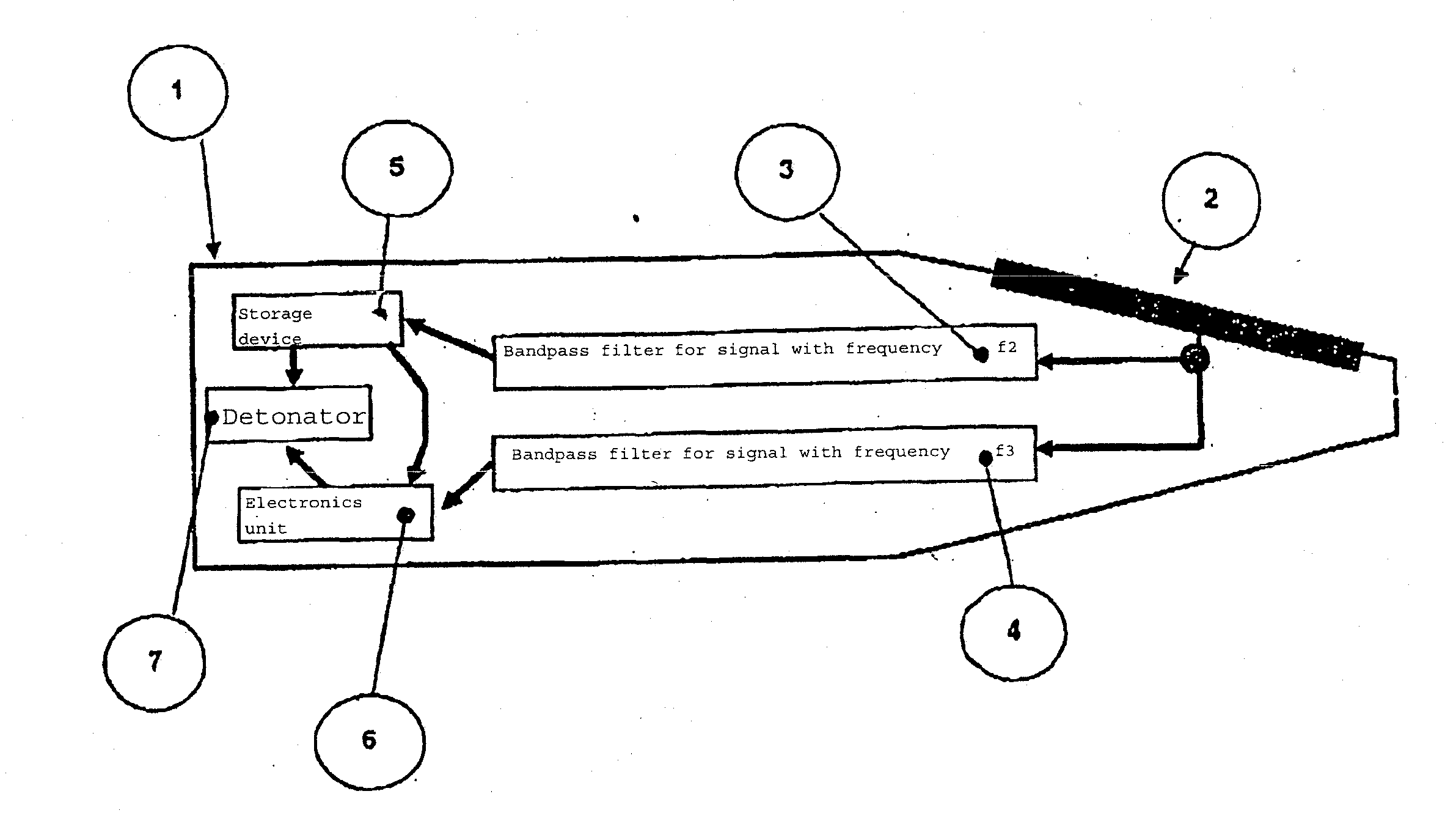
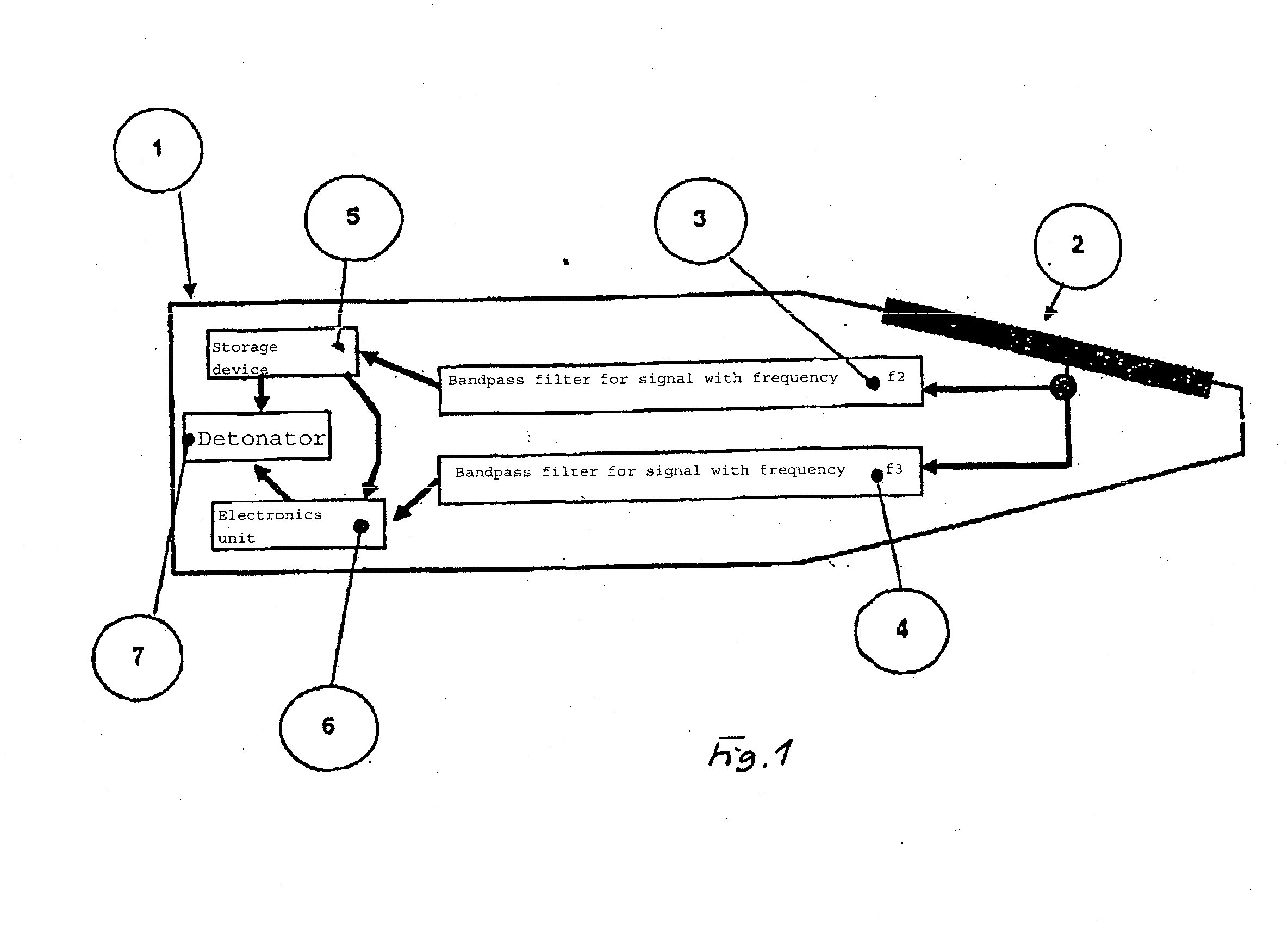
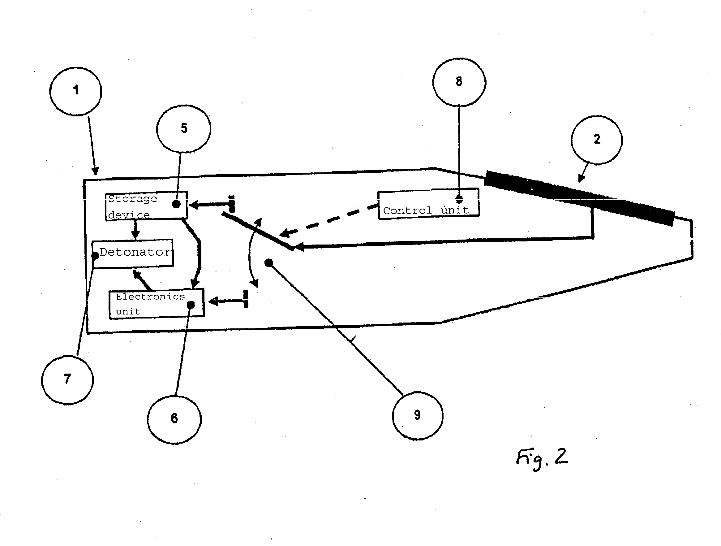
[0030]FIG. 1 through 3 show a projectile or round of ammunition 1 with at least one sensor 2 for receiving a programming signal with the frequency f3 and / or an energy transmission signal with the frequency f2. The sensor can be, for example, a coil for an inductive signal transmission and / or an electrode for a capacitive signal transmission. The number 7 labels a detonator (electric), which is electrically connected to an electronics unit (processor) 6 and to an energy storage device 5. The signal with the frequency f2 supplies the energy storage device 5 with energy, and the signal with the frequency f3 programs the electronics unit 6, for example with the detonation time. The energy storage device 5 supplies power to the electronics unit 6 and the detonator 7.

[0031]In the exemplary embodiment, the energy transmission can be tuned to the signal of the programming. In this design in FIG. 1, the programming signal with frequency f3≠f2 is used so that the same sensor 2 can be used for...


PUM


Abstract

A programmable ammunition which receives a program as well as energy transmission is provided. The ammunition also comprises an energy store, an electronic system and an ignition in addition to at least one sensor for capturing the signal emitted for the program, the signal having a frequency which is transmitted further to the electronic system. The ammunition is also combined with an energy transfer unit in such a manner that an additional signal having a frequency is guided to the energy unit by the same the sensor and / or an additional sensor and is charged. Programming and the energy transmission occurs when the projectile passes through a weapon barrel, a muzzle brake or similar which is operated as a waveguide below the threshold frequency.

Description

[0001]This nonprovisional application is a continuation of International Application No. PCT / EP2011 / 000389, which was filed on Jan. 28, 2011, and which claims priority to German Patent Application No. DE 10 2010 006 530.7, which was filed in Germany on Feb. 1, 2010, and which are both herein incorporated by reference.BACKGROUND OF THE INVENTION[0002]1. Field of the Invention[0003]The present invention relates to the challenge of programming a projectile during passage through the barrel or the like. In addition, provision is also made for implementing the transmission of energy to the projectile during passage through the barrel, etc.[0004]2. Description of the Background Art[0005]For programmable ammunition, information must be communicated to the projectile—which is to say programmed into it—concerning its detonation time and / or flight path. In systems in which the detonation time is calculated from the measured muzzle velocity V0, the information can be relayed no earlier than at...

Claims


Application Information

Patent Timeline
IPC IPC(8): F42C11/06
CPCF42C11/065F42C11/008F42C17/04F42C11/00F42C11/06
Inventor FRICK, HENRY ROGER
Owner OERLIKON CONTRAVES BESCHRAENKTER HAFTUNG
Learn More