

Capacitive transducer, capacitive transducer manufacturing method, and object information acquisition apparatus
a technology of capacitive transducer and manufacturing method, which is applied in the direction of mechanical vibration separation, instruments, specific gravity measurement, etc., can solve the problems of uneven warping of vibrating film, and affecting the performance of vibrating film
- Summary
- Abstract
- Description
- Claims
- Application Information
AI Technical Summary
Benefits of technology
Problems solved by technology
Method used
Image

Examples
example 1
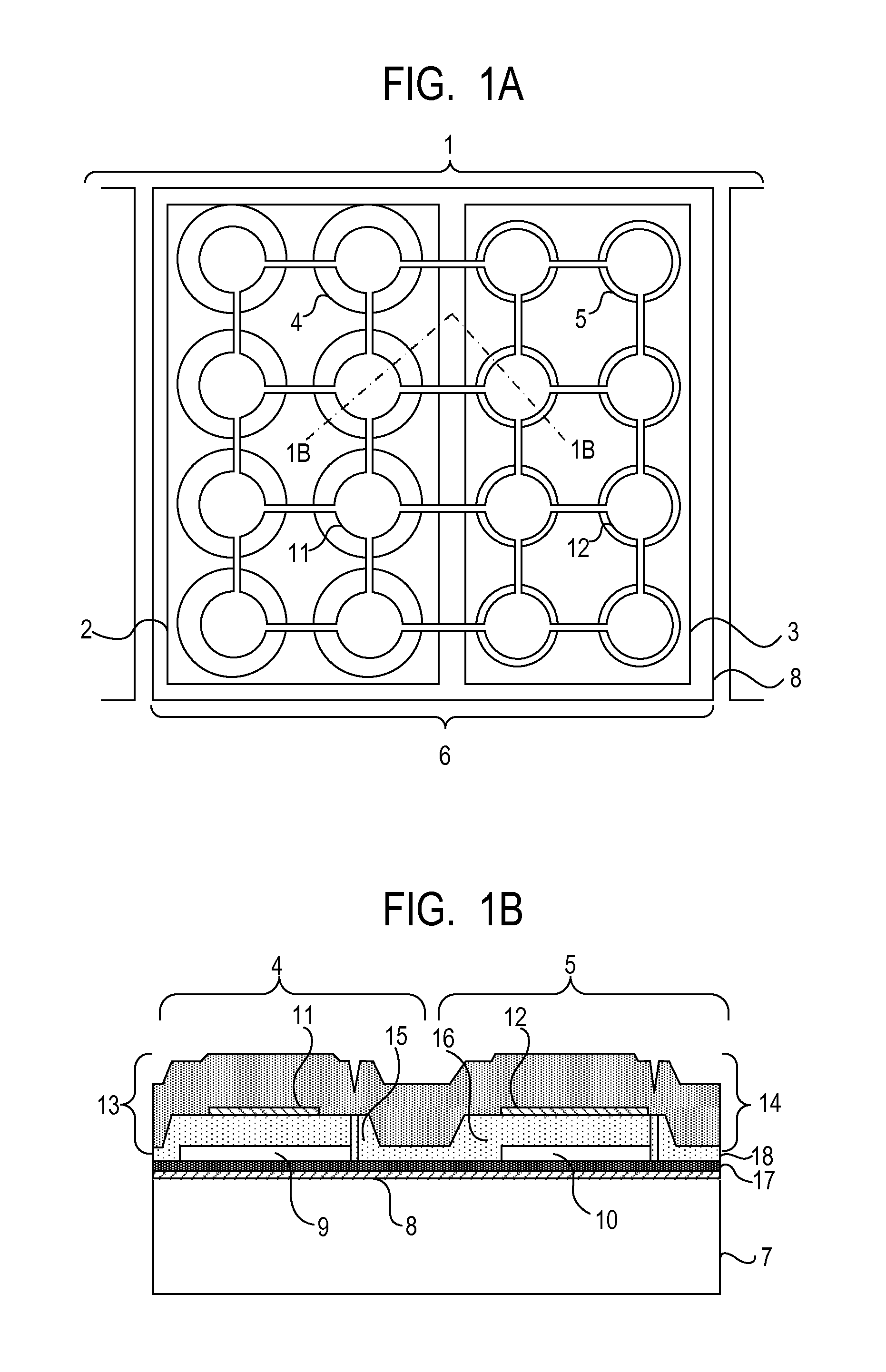
[0032]A capacitive transducer according to Example 1 of the present invention is now described. FIGS. 1A and 1B illustrate Example 1. The cell group 2 includes eight cells 4 and the cell group 3 includes eight cells 5, but the numbers of the cells are not limited thereto. However, if the number of cells in one of the cell groups is too large, the effect of increasing the band is reduced, and hence it is desired that the occupied areas of the cell groups 2 and 3 be as equal as possible.
[0033]As illustrated in FIG. 1A, when the vibrating films 13 and 14 or the gaps 9 and 10 in different kinds of cells are formed to be circular, the diameter thereof is 20 to 50 micrometers. The diameter of the gap 9 is larger than the diameter of the gap 10 in FIGS. 1A and 1B, but may be equal to each other. In this case, the area ratio of the second electrode 11 to the gap 9 is smaller than the area ratio of the second electrode 12 to the gap 10. Therefore, when the gap 9 and the gap 10 have equal are...
example 2
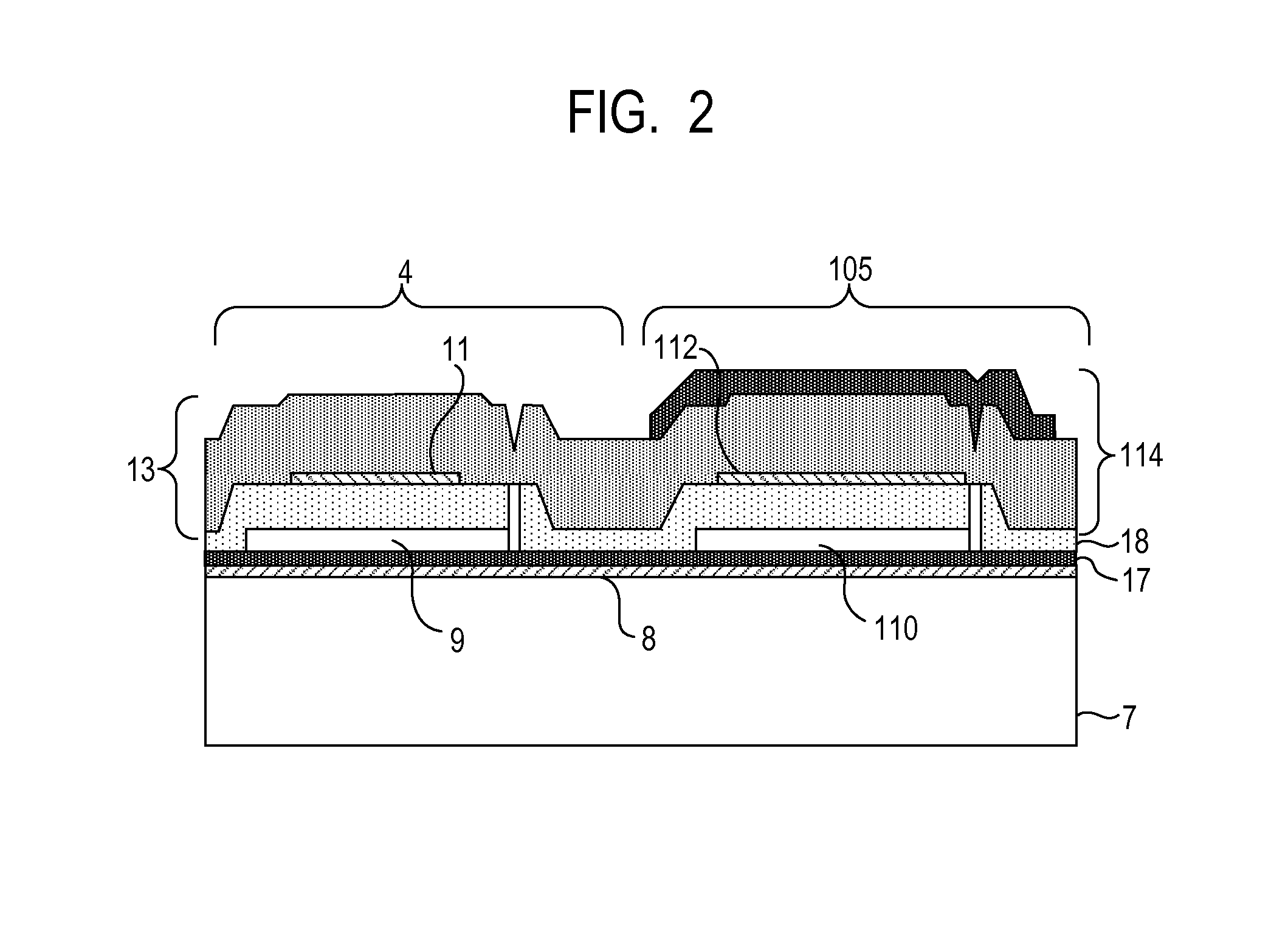
[0038]A capacitive transducer according to Example 2 of the present invention is now described. Example 2 is a modification of Example 1. FIG. 2 illustrates Example 2, illustrating the same cross-section as in FIG. 1B. The cell 4 in the cell group 2 has the same structure as in Example 1.
[0039]In a cell 105, a gap 110 has a diameter equal to that of the gap 9, and a second electrode 112 has a diameter equal to that of the second electrode 12 in Example 1. The structure of a vibrating film 114 is the same as that of the cell 4 in that the thickness below the second electrode 112 is 400 nanometers, but different in that the thickness of a silicon nitride film on the top of the second electrode is 1,100 nanometers. In this case, the vibrating film 114 has a spring constant of 77 kN / m, which is larger than the spring constant (37 kN / m) of the vibrating film 13. In this manner, the band is increased similarly to Example 1.
[0040]The thickness of the silicon nitride film above the second e...
example 3
[0042]A probe including the capacitive transducer described in the above-mentioned embodiment or examples is applicable to an object information acquisition apparatus using acoustic waves. An acoustic wave from an object is received by the capacitive transducer, and an output electric signal is used to acquire object information that reflects an optical property value of the object, such as a light absorption coefficient.
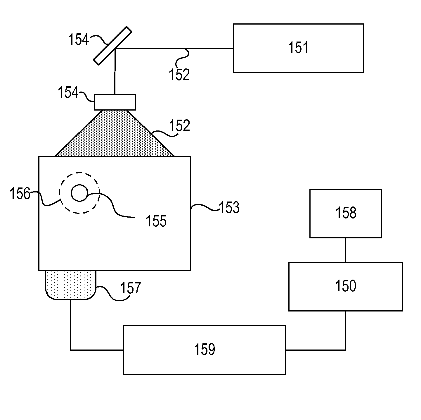
[0043]FIG. 4 illustrates an object information acquisition apparatus of Example 3 using a photoacoustic effect. Pulsed light 152 emitted from a light source 151 for generating light in the form of a pulse irradiates an object 153 via an optical member 154 such as a lens, a mirror, or an optical fiber. A light absorber 155 inside the object 153 absorbs energy of the pulsed light to generate a photoacoustic wave 156 as an acoustic wave. A probe 157, which is equipped with a casing that accommodates the capacitive transducer having broadband characteristics of the pres...
PUM
 Abstract
Description
Claims
Application Information