Grinding tool with eccentric rotation shaft

a technology of eccentric rotation and grinding tool, which is applied in the direction of gear teeth, gear-teeth manufacturing apparatus, slip coupling, etc., can solve the problems of large energy loss, inefficient structure, and mark and scratch on the surface of workpieces, and achieve smooth ground surface, beautiful delustered surface, and efficient operation

Active Publication Date: 2014-01-09
KEITECH
View PDF4 Cites 2 Cited by
  • Summary
  • Abstract
  • Description
  • Claims
  • Application Information

AI Technical Summary

Benefits of technology

[0014]The clutch members of the grinding tool described above have a sliding surface that is capable of sliding and capable of transmitting a driving force. When grinding is not performed and the grinding disc is unloaded, the sliding surface of the clutch members performs a braking function to prevent a considerable increase in the rotational speed of the grinding disc about its axis. When grinding is performed and a load is applied to the grinding disc, a driving force from the rotary disc is transmitted to the grinding disc by using the friction of the sliding surface, and therefore the rotational speed of the grinding disc about its axis can be maintained. Thus, during a grinding operation, the rotational speed of the rotary disc, that is, the rotational speed of the grinding disc, can be adjusted by adjusting the rotational speed of the motor, and the rotational speed of the grinding disc about its axis can also be adjusted by appropriately adjusting a force with which the abrasive member attached to the grinding disc is pressed against a surface of a workpiece. Accordingly, the grinding disc can perform a rotational motion in which a rotational motion about its axis and an orbital motion are combined in a complex way.
[0015]Therefore, by using the grinding tool according to the present invention, when grinding a workpiece by a large grinding amount, a smoothly ground surface can be obtained despite the large grinding amount due to the complex and active rotational motion of the grinding disc. Moreover, a beautifully delustered surface can be obtained, and the operation can be efficiently performed. Furthermore, buffing can be performed without generating marks and patterns on a buffed surface. With the grinding tool, although rotation of the grinding disc is complex and irregular, the direction of rotation of the grinding disc about its axis is the same as the direction of rotation of the rotary disc, so that driving energy loss is small, shock due to an instantaneous change in the direction of rotation does not occur during grinding, and a grinding operation can be performed safely. Accordingly, the grinding tool according to the present invention can be preferably used as a tool for grinding, which is called a grinder or a sander, and as a tool for polishing, which is called a polisher.

Problems solved by technology

As a result, marks and scratches are formed on the surface of the workpiece.
Such a structure is inefficient because a brake is applied to the grinding disc before the rotational energy of the drive shaft is transmitted to a workpiece, and therefore energy loss is large.
Therefore, a large shock occurs, and the shock may affect a surface of a workpiece and may cause danger to an operator.
Furthermore, the rotational speed of the grinding disc becomes constant relative to that of driving rotation, that is, the grinding disc does not rotate irregularly and smoothly.
Therefore, this structure does not provide the function of a grinding tool having an eccentric rotation mechanism.
Moreover, the grinding tool, in which connection and disconnection of a locking device are performed and a clutch and the like, are used, has a complex mechanism.
Furthermore, as in the case of PTL 1, a large shock occurs because the direction of rotation of the sanding disc changes instantaneously during a grinding operation, and the shock may affect a surface of a workpiece or may cause danger to an operator.
Therefore, the grinding tool has a problem about the durability, which arises due to the structure of the bearing.

Method used


Image

  • Grinding tool with eccentric rotation shaft
  • Grinding tool with eccentric rotation shaft
  • Grinding tool with eccentric rotation shaft

Examples


Embodiment Construction

[0022]Embodiments of the present invention will be described. in detail with reference to the drawings.

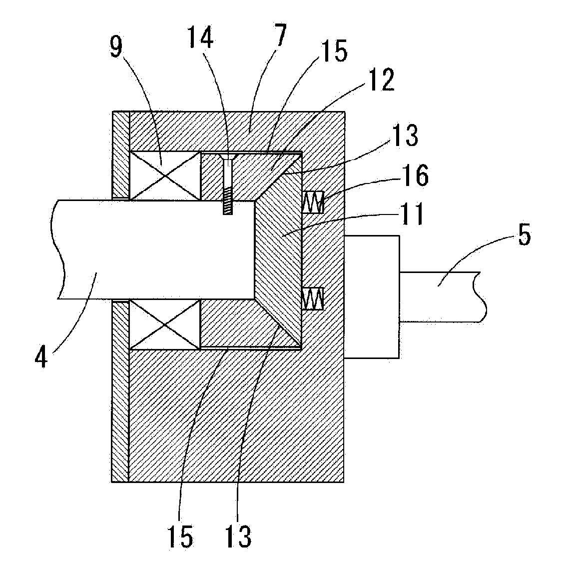
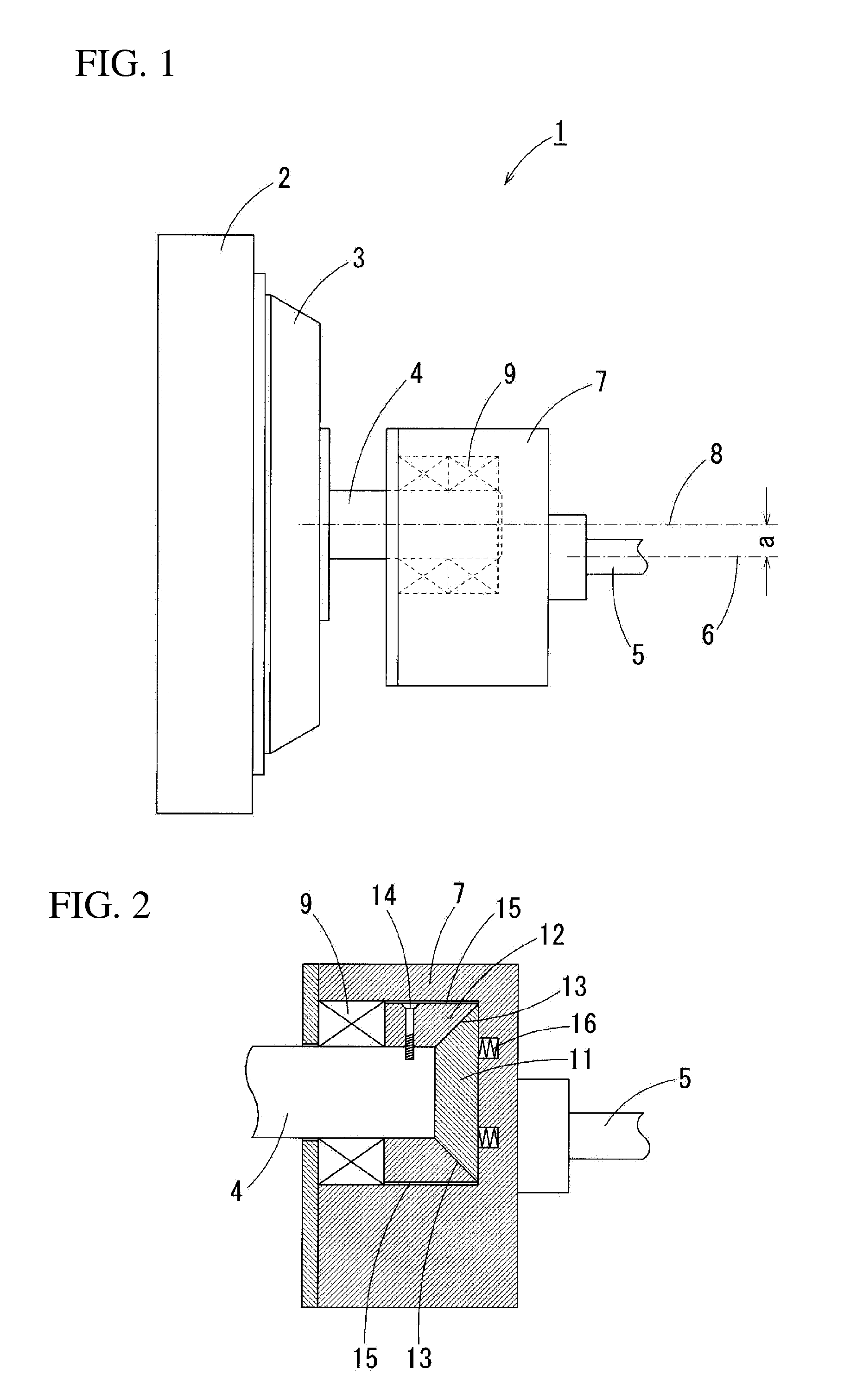
[0023]FIG. 2 is a sectional view of clutch members attached to a rotary disc and to an eccentric rotation shaft according to the present invention. Although not illustrated in FIG. 2, a grinding disc 3 is fixed to an end of an eccentric rotation shaft 4, and an abrasive member 2 is attached to the grinding disc 3 as in FIG. 1. Likewise, although not illustrated, a driving motor is connected to an end of a drive shaft 5. A rotary disc 7 is rotated by a driving force of a motor. As described above with reference to FIG. 1, the eccentric rotation shaft 4 is attached to a position that is eccentric with respect to the drive shaft 5. When the motor rotates the drive shaft 5, the rotary disc 7 rotates and the eccentric rotation shaft 4 performs an orbital motion. Moreover, the eccentric rotation shaft 4, which is attached to the rotary disc 7 through a bearing 9, performs a rotational mo...


PUM


Abstract

A grinding tool with an eccentric rotation shaft of a grinding disc with attached grinding material installed via a hearing at a position that is shifted from the central drive shaft line of a rotating disc fixed on a drive shaft, comprises a clutch in which a grinding disc-side clutch component member installed on the grinding disc or on the eccentric rotation shaft that is fixed to the grinding disc and a rotating disc-side clutch component member installed on the rotating disc are linked via a sliding surface capable of sliding and of transmitting the drive force.
The rotation rate of the grinding disc is limited to a stable range of rotation rates, preventing extreme elevation in the rotation rate and extreme reduction in the rotation rate; the workpiece is ground efficiently; and the tool does riot generate marks or patterns on the ground surface.

Description

TECHNICAL FIELD[0001]The present invention relates to grinding tools, such as a sander, a grinder, and a polisher, which are machine tools for machining a surface of a workpiece by grinding or polishing the surface. In particular, the present invention relates to a so-called double action grinding tool or a random action grinding tool in which a rotation shaft of a grinding disc is disposed at an eccentric position displaced by a predetermined distance from the axis of a drive shaft.BACKGROUND ART[0002]With a grinding tool in which a rotation shaft of a grinding disc is rotatably attached at a position that is eccentric with respect to the axis of a drive shaft of a driving motor, the grinding disc performs an orbital motion around the drive shaft and a rotational motion about the rotation shaft. Therefore, such a grinding tool is usually called a “double action sander grinding tool” or a “random action grinding tool”. FIG. 1 illustrates an eccentric rotation mechanism of such an ex...

Claims


Application Information

Patent Timeline
Patent Type & Authority Applications(United States)
IPC IPC(8): B24D7/16
CPCB24D7/16B24B23/03B24B47/12F16D7/028
Inventor KANEKO, KOJI
Owner KEITECH
Why Eureka
Try Eureka