Power supply device, power-supply-device separator, and power-supply-device-equipped vehicle

a technology of power supply device and separator, which is applied in the direction of propulsion of batteries/cells, cell components, batteries, etc., can solve the problems of reducing cooling efficiency, reducing the cooling performance of the battery block 210, and forming gaps between the bottom surface of the battery block and the base plate, so as to improve heat conduction, improve the cooling performance, and efficiently cool the battery cell

Inactive Publication Date: 2014-01-16
SANYO ELECTRIC CO LTD
View PDF2 Cites 41 Cited by
  • Summary
  • Abstract
  • Description
  • Claims
  • Application Information

AI Technical Summary

Benefits of technology

[0041]According to this construction, when the battery block is securely held, the bearing performance of the separator can be increased. In addition to this, the contact parts of the separator, which are in contact with the battery cell, can be thin. Therefore, it is possible to improve the heat conduction.
[0042]In a power supply device according to a sixteenth aspect of the present invention, a forcedly-gas-blowing mechanism can be further provided which forcedly blows cooling gas to the gas-flowing paths of the battery block thereby cooling the battery cells.
[0043]According to this construction, since cooling gas blown by the forcedly-gas-blowing mechanism does not flow through the gap between the battery block and the base plate, it can be ensured that the cooling gas flows through the gas-flowing paths of the battery block. Therefore, it is possible to efficiently cool the battery cells.

Problems solved by technology

As a result, a problem will arise in that the cooling performance for cooling the battery block 210 decreases.
As a result, the cooling efficiency will decrease.
As a result, gaps may be formed between the bottom surfaces of the battery blocks and the base plate.
Consequently, a problem will arise in that the cooling efficiency decreases.

Method used


Image

  • Power supply device, power-supply-device separator, and power-supply-device-equipped vehicle
  • Power supply device, power-supply-device separator, and power-supply-device-equipped vehicle
  • Power supply device, power-supply-device separator, and power-supply-device-equipped vehicle

Examples


case 50

(Exterior Case 50)

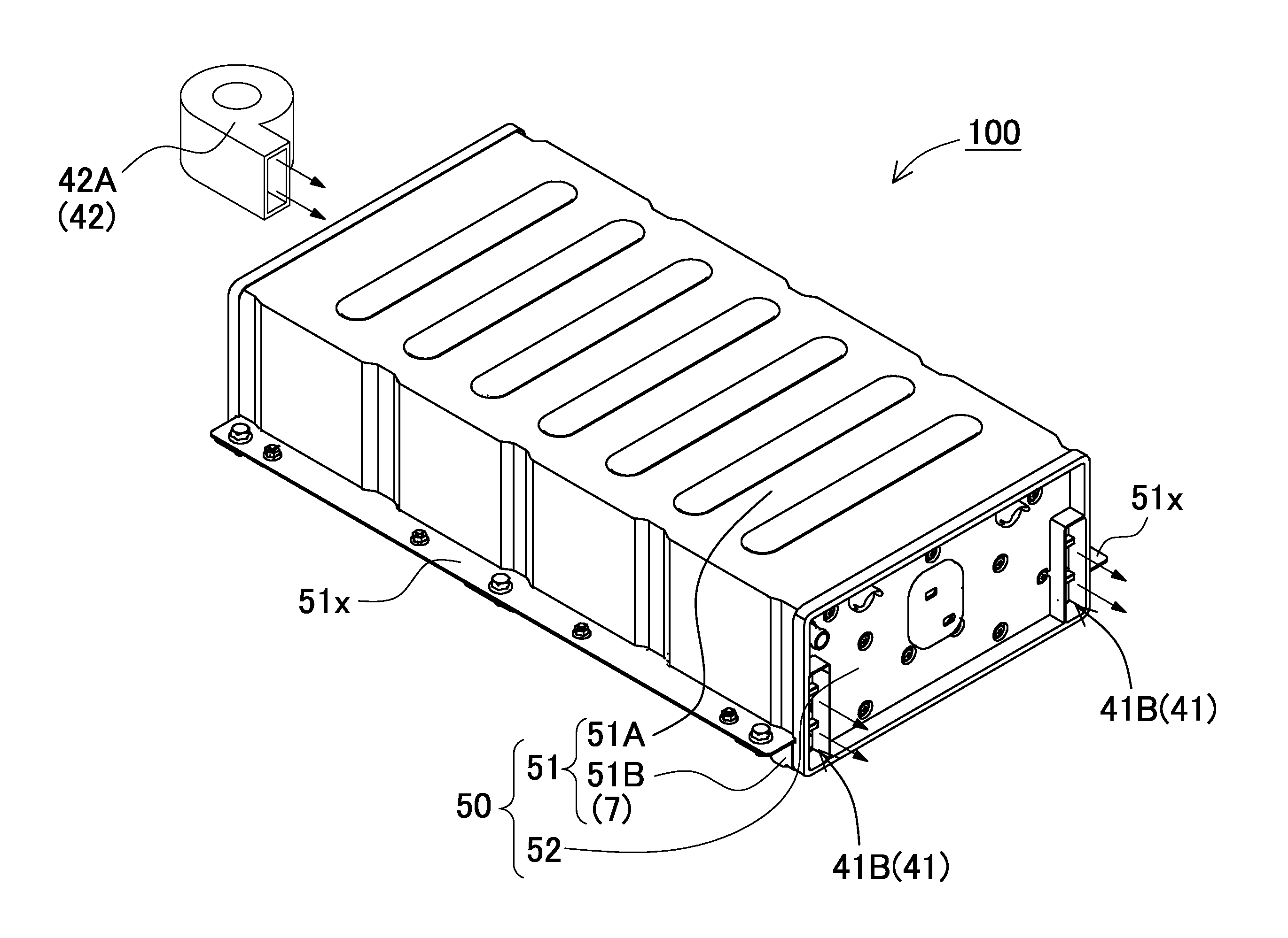
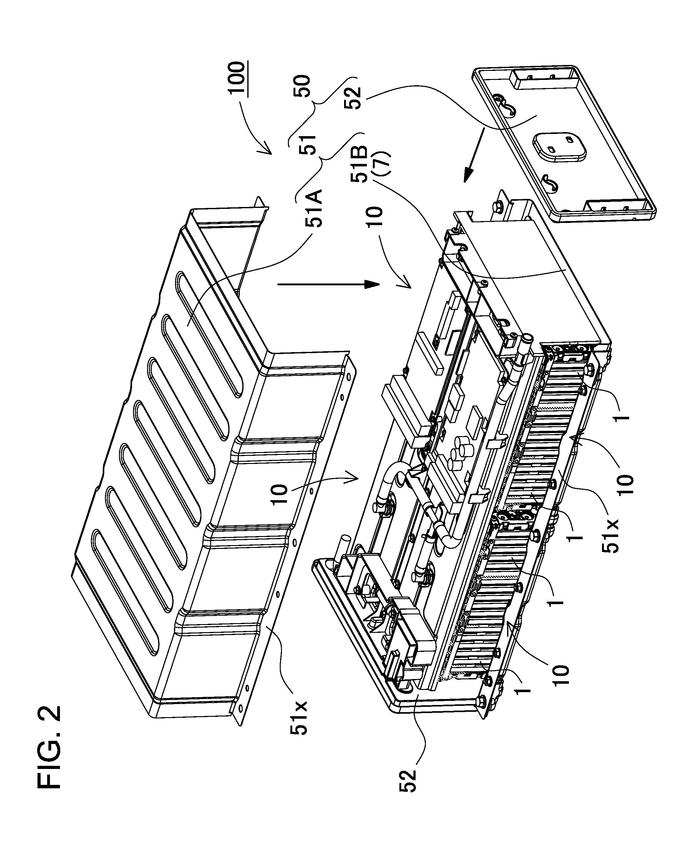
[0086]The exterior case 50 include an exterior case portion 51 that includes sectional rectangular U-shaped lower and upper case sections 51B and 51A. The exterior case portion 51 covers the upper and lower surfaces and side surfaces of an assembly of the battery blocks 10. The end surfaces of the exterior case portion 51 are closed by end surface covers 52. In addition, flanges 51x are formed on the longitudinal side surfaces of the exterior case portion 51, and protrude perpendicularly to the longitudinal side surfaces. The flanges 51x facilitate installation of the power supply device on vehicles. The flange 51x has screw holes that are open for receiving screws. Thus, the power supply device can be easily fastened by screws that engage with the screw holes.

(Base Plate 7)

[0087]The base plate 7 has a plate shape onto which the battery block 10 can be mounted. The battery block 10 is fastened to the one surface of the base plate 7 so that the battery block 10 is p...


PUM

PropertyMeasurementUnit
thicknessaaaaaaaaaa
thicknessaaaaaaaaaa
thicknessaaaaaaaaaa

Abstract

A power supply includes batteries, separators, a base plate, and an elastic seal. The batteries have a rectangular-box exterior shape. The separators are interposed between the batteries. The batteries are arranged side by side. The base plate has one surface onto which a battery block of the batteries is fastened. The seal is interposed between a bottom surface of the battery block and an upper surface of the base plate, thereby airtightly closing gaps between them. The separator has recessed parts that form gas-flowing paths between the batteries so that cooling gas can flow along surfaces of the batteries when the separator is interposed between the batteries. The separator includes a plate-shaped bottom cover that is arranged on a bottom surface side of the separator, and protrudes in the side-by-side arrangement direction of the batteries. The bottom cover has a recessed part that is arranged on the seal.

Description

BACKGROUND OF THE INVENTION[0001]1. Field of the Invention[0002]The present invention mainly relates to a power supply device that can be used as a large current power supply for an electric motor for driving cars such as a hybrid car and an electric vehicle, and as electric power storages for home use and manufacturing plants, and a separator that can be used for this type of power supply device. The present invention also relates to a vehicle and an electric power storage including this power supply device.[0003]2. Description of the Related Art[0004]Power supply devices such as battery packs for vehicles are required which can supply high electric power. In order to accommodate a number of battery cells in limited space, the high power supply devices generally include rectangular batteries, which can efficiently occupy space. The rectangular battery includes electrode members, and a rectangular exterior case that accommodates the current collectors, and a sealing plate that seals...

Claims


Application Information

Patent Timeline
Patent Type & Authority Applications(United States)
IPC IPC(8): H01M10/50B60K1/04H01M2/18H01M50/209H01M50/271
CPCH01M10/0481H01M2220/20H01M10/625H01M10/653H01M10/6563H01M10/647H01M10/6557H01M10/651H01M10/613B60L50/64Y02E60/10H01M50/271H01M50/209Y02T10/70
Inventor KOMAKI, TSUYOSHIKURIYAMA, TOMOHISA
Owner SANYO ELECTRIC CO LTD
Why Eureka
Try Eureka