Edge exclusion control with adjustable plasma exclusion zone ring

a plasma exclusion and control technology, applied in the field of wafer processing equipment, can solve the problems of large edge exclusion, increase in cost and effort used to etch a substrate, and unconfinement of plasma within the gap, and achieve the effect of reducing the effect of plasma

Active Publication Date: 2014-01-23
LAM RES CORP
View PDF0 Cites 163 Cited by
  • Summary
  • Abstract
  • Description
  • Claims
  • Application Information

AI Technical Summary

Benefits of technology

[0009]Also, sometimes, when the upper PEZ ring is clamped to the upper electrode to move with the upper electrode, during movement of the upper electrode, a gap between the upper PEZ ring and the substrate increases beyond a certain distance, e.g., 0.6 millimeters (mm), to often cause unconfinement of plasma within the gap. By controlling the movement of the upper PEZ ring independent of movement of the upper electrode, the gap is controlled to avoid the increase in the distance. The smaller the gap, the less the plasma encroachment, which leads to a smaller edge exclusion of a surface area of the substrate from a bevel edge of the substrate. The edge exclusion occurs to perform a processing operation, e.g., cleaning operation, etching operation, depositing operation, etc. on the surface area from the bevel edge. The larger the gap, the more the plasma encroachment, which leads to a large edge exclusion. In a number of embodiments, a gap between the upper electrode and the substrate is maintained between 0.35-0.4 mm and the upper PEZ ring is moved to control edge exclusion and to avoid plasma unconfinement issues. Also, in various embodiments, a gap between the upper electrode extension and the substrate is maintained between 0.35-0.4 mm and the upper PEZ ring is moved to control edge exclusion and to avoid plasma unconfinement issues.

Problems solved by technology

Such change in hardware results in an increase in cost and effort used to etch a substrate.
Also, sometimes, when the upper PEZ ring is clamped to the upper electrode to move with the upper electrode, during movement of the upper electrode, a gap between the upper PEZ ring and the substrate increases beyond a certain distance, e.g., 0.6 millimeters (mm), to often cause unconfinement of plasma within the gap.
The larger the gap, the more the plasma encroachment, which leads to a large edge exclusion.

Method used


Image

  • Edge exclusion control with adjustable plasma exclusion zone ring
  • Edge exclusion control with adjustable plasma exclusion zone ring
  • Edge exclusion control with adjustable plasma exclusion zone ring

Examples


Embodiment Construction

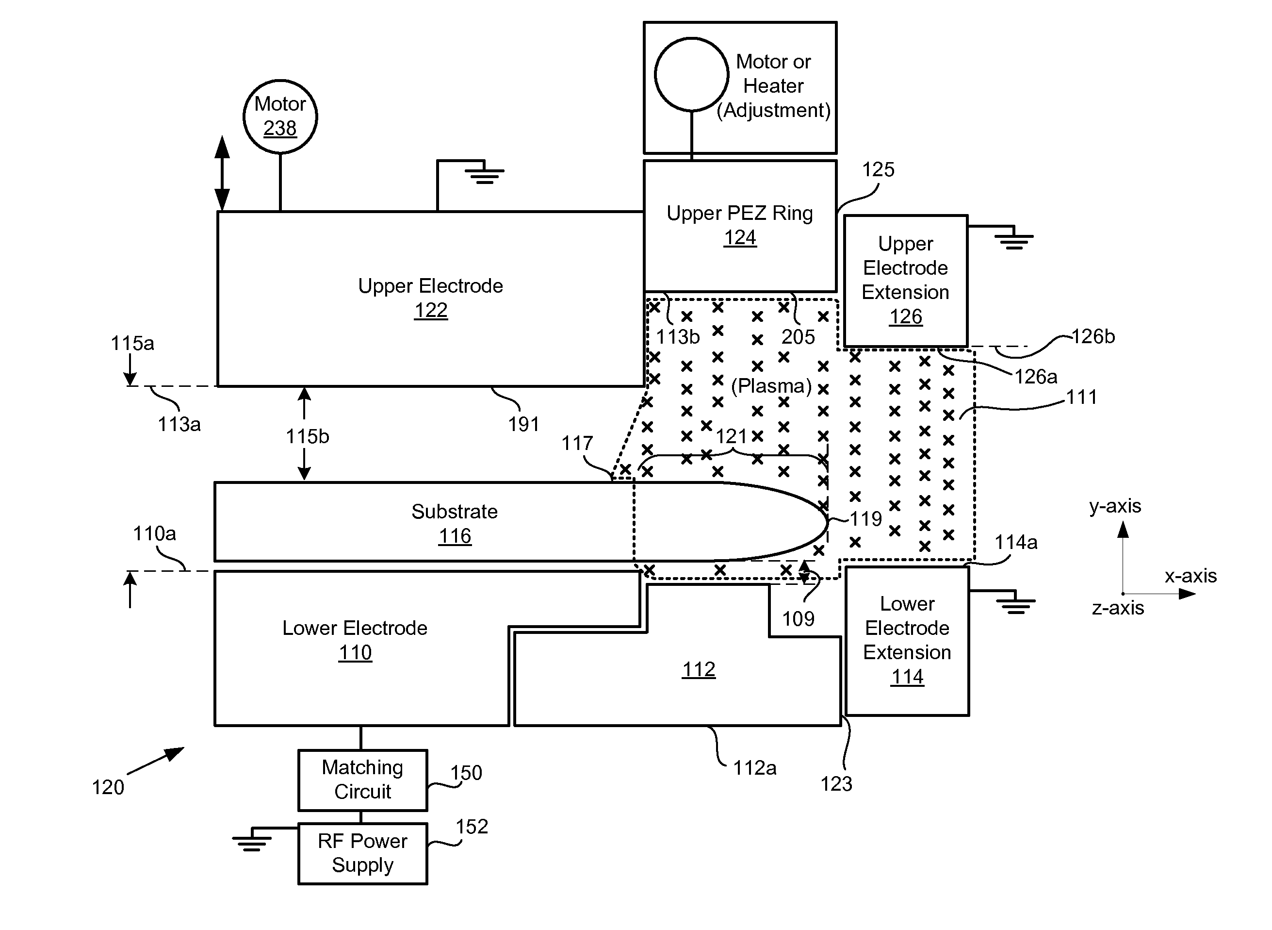
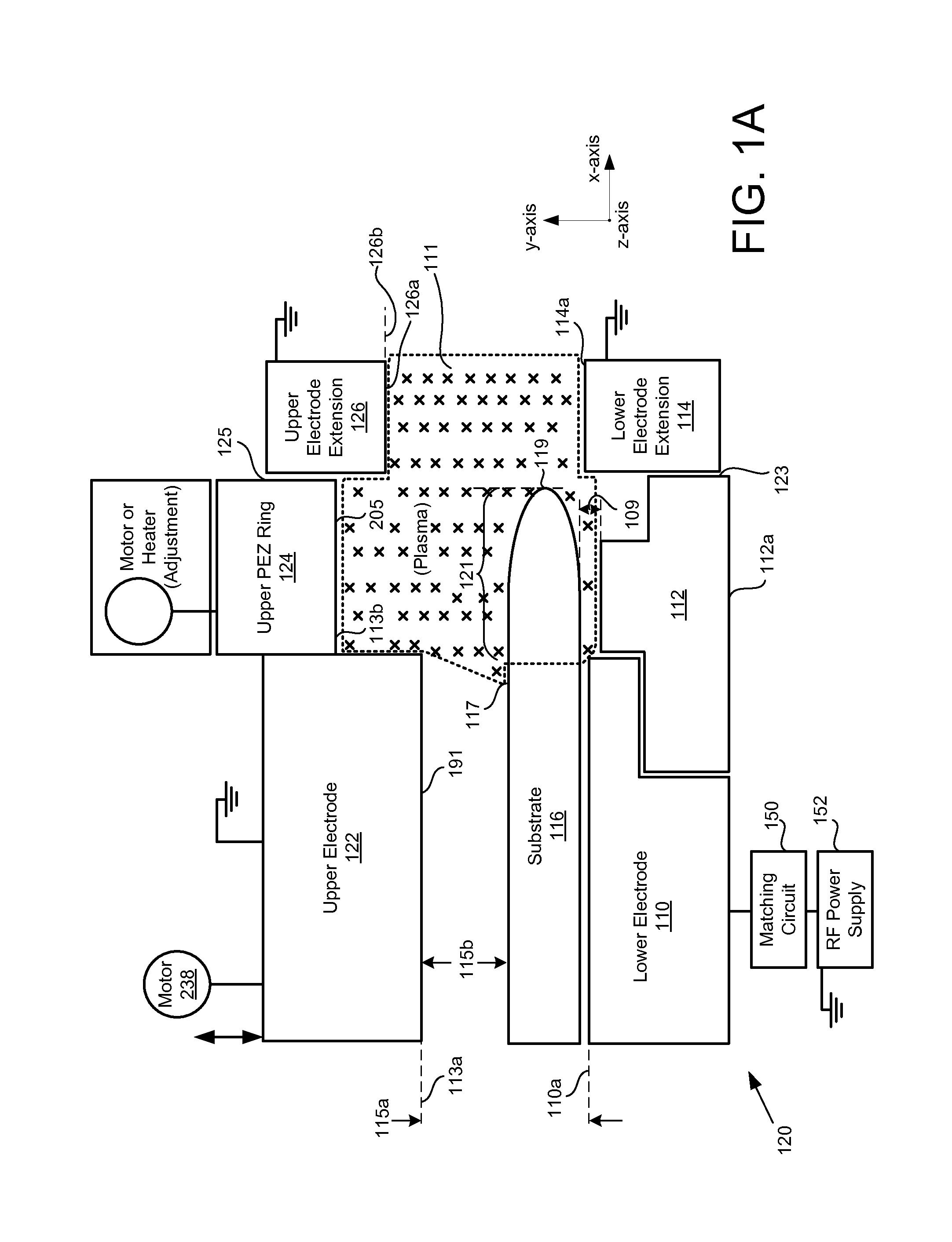
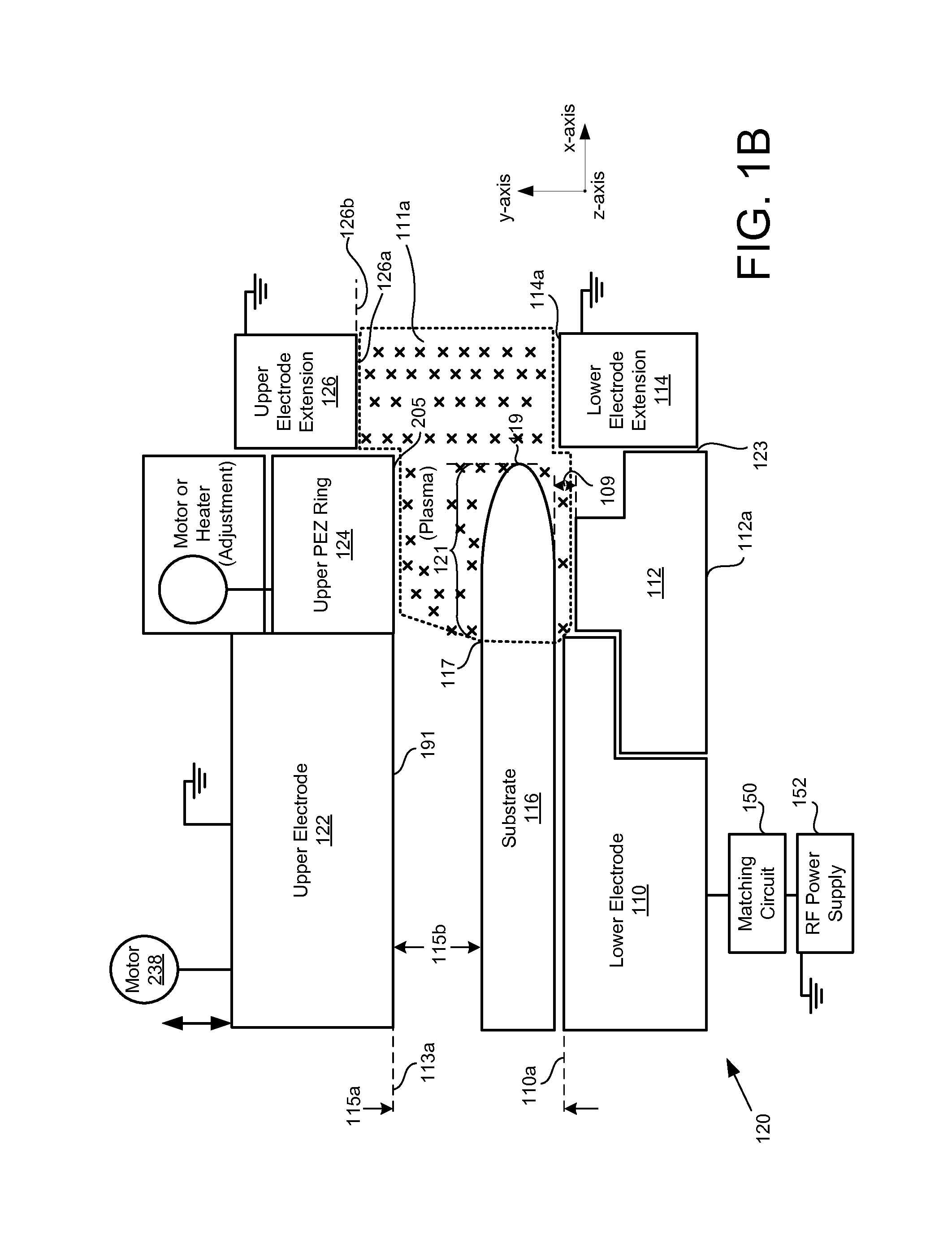
[0037]The following embodiments describe systems and methods for edge exclusion control with movement of plasma exclusion zone ring. It will be apparent that the present embodiments may be practiced without some or all of these specific details. In other instances, well known process operations have not been described in detail in order not to unnecessarily obscure the present embodiments.

[0038]FIG. 1A is a diagram of an embodiment of a system 120 for changing a gap associated with an edge processing region 111. The system 120 includes an upper electrode assembly, which further includes an upper electrode 122, an upper plasma exclusion zone (PEZ) ring 124, and an upper electrode extension (UEE) 126, which has a lower surface 126a at a level 126b. It should be noted that in some embodiments, a PEZ ring and a “dielectric ring” are used interchangeably herein. The upper PEZ ring 124 is located horizontally between the upper electrode 122 and the UEE 126. Also, the upper PEZ ring 124 is...


PUM

PropertyMeasurementUnit
distanceaaaaaaaaaa
distanceaaaaaaaaaa
frequenciesaaaaaaaaaa

Abstract

Systems and methods for edge exclusion control are described. One of the systems includes a plasma chamber. The plasma processing chamber includes a lower electrode having a surface for supporting a substrate. The lower electrode is coupled with a radio frequency (RF) power supply. The plasma processing chamber further includes an upper electrode disposed over the lower electrode. The upper electrode is electrically grounded. The plasma processing chamber includes an upper dielectric ring surrounding the upper electrode. The upper dielectric ring is moved using a mechanism for setting a vertical position of the upper dielectric ring separate from a position of the upper electrode. The system further includes an upper electrode extension surrounding the upper dielectric ring. The upper electrode extension is electrically grounded. The system also includes a lower electrode extension surrounding the lower dielectric ring. The lower electrode extension is arranged opposite the upper electrode extension.

Description

BACKGROUND[0001]1. Field of the Invention[0002]The present embodiments relate to wafer processing apparatus, and more particularly, apparatus, methods, and computer programs for edge exclusion control with adjustable plasma exclusion zone ring.[0003]2. Description of the Related Art[0004]The manufacturing of integrated circuits includes immersing silicon substrates (wafers) containing regions of doped silicon in chemically-reactive plasmas, where the submicron device features (e.g., transistors, capacitors, etc.) are etched onto the surface. Once the first layer is manufactured, several insulating (dielectric) layers are built on top of the first layer, where holes, also referred to as vias, and trenches are etched into the material for placement of the conducting interconnectors. The chemically-reactive plasmas are created in a plasma chamber. This is an illustration of use of etching. Etching may be used to clean the substrate or remove residues from a surface of the substrate.[00...

Claims


Application Information

Patent Timeline
Patent Type & Authority Applications(United States)
IPC IPC(8): C23F1/08B08B7/00
CPCH01J37/32091H01J37/32385H01J37/32568H01J37/32623H01J37/32862H01L21/02H05H1/38B08B7/0035H01J2237/334H01J2237/335
Inventor KIM, KEECHANKIM, YANSUNG
Owner LAM RES CORP
Why Eureka
Try Eureka