Disk drive suspension

Active Publication Date: 2014-01-23
NHK SPRING CO LTD
View PDF5 Cites 45 Cited by
  • Summary
  • Abstract
  • Description
  • Claims
  • Application Information

AI Technical Summary

Benefits of technology

[0011]Accordingly, the object of this invention is to provide a disk drive suspension comprising a microactuator element of PZT or the like on a gimbal portion and configured so that the pivot c

Problems solved by technology

Therefore, the thickness of a head portion of a head gimbal assembly increases, making it difficult to reduce the thickness of a disk drive.
Thus, microactuator elements of a fragile material such as PZT are liable to be broken.
Accordingly, there is a problem that

Method used


Image

  • Disk drive suspension
  • Disk drive suspension
  • Disk drive suspension

Examples


Embodiment Construction

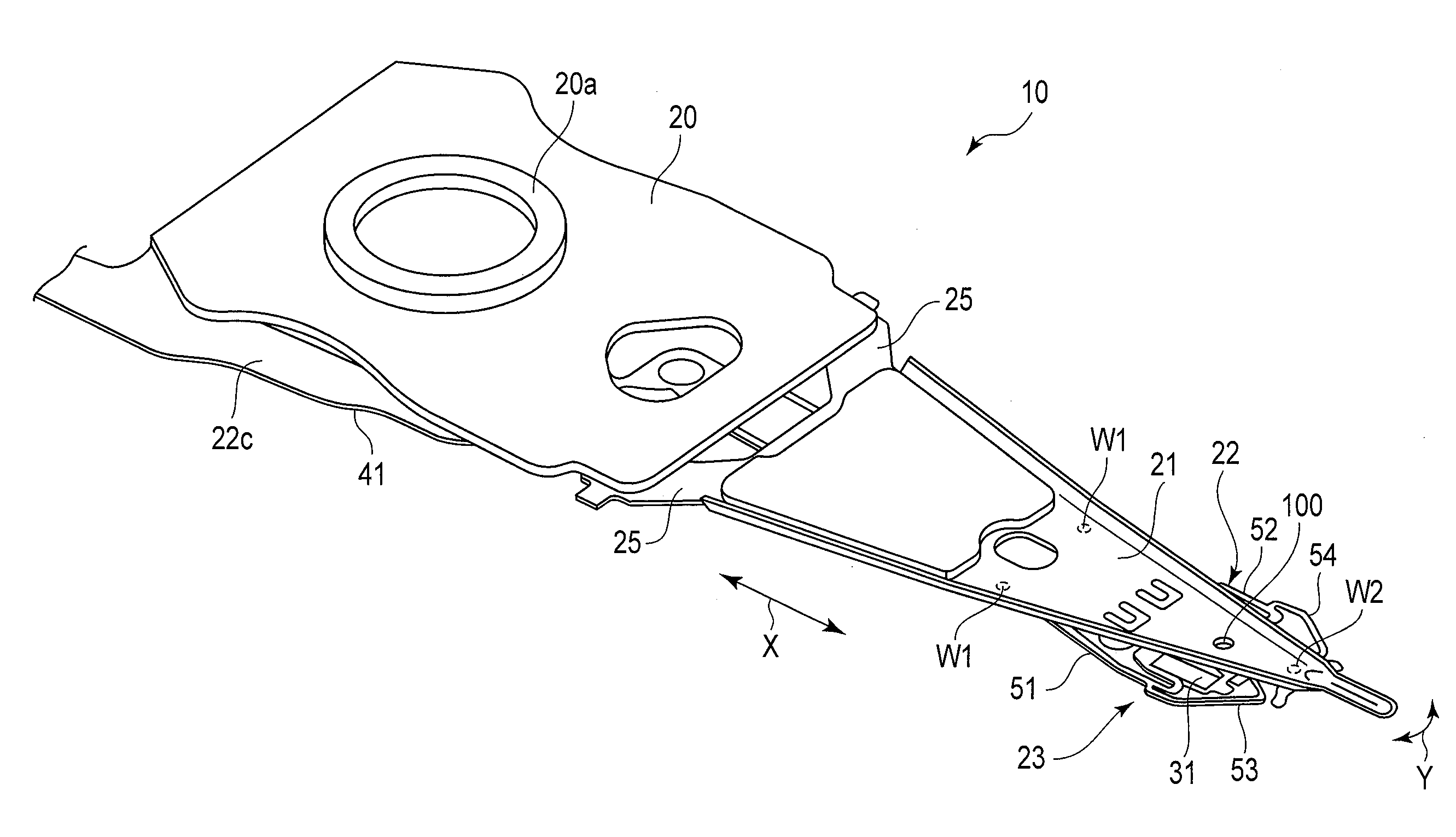
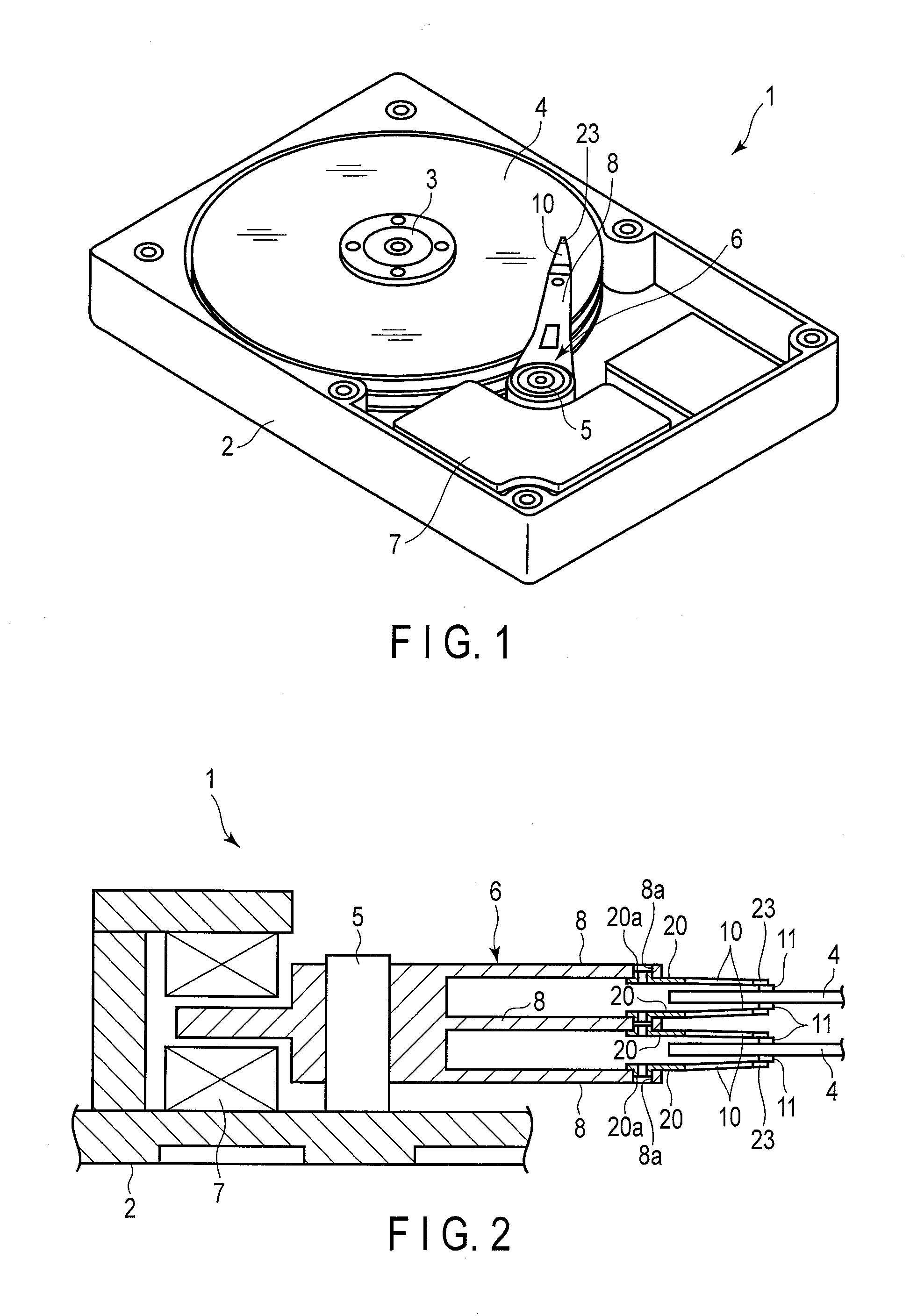
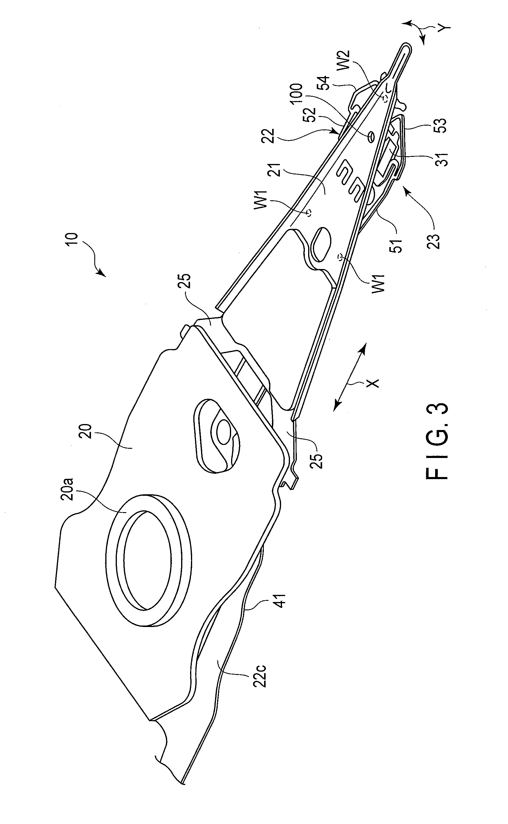
[0032]A disk drive suspension according to a first embodiment of the present invention will now be described with reference to FIGS. 1 to 11.

[0033]A disk drive (HDD) 1 shown in FIG. 1 comprises a case 2, disks 4 rotatable about a spindle 3, carriage 6 turnable about a pivot 5, positioning motor (voice coil motor) 7 for actuating the carriage 6, etc. The case 2 is sealed by a lid (not shown).

[0034]FIG. 2 is a sectional view schematically showing a part of the disk drive 1. As shown in FIGS. 1 and 2, the carriage 6 comprises arms (carriage arms) 8. A suspension 10 is mounted on the distal end portion of each arm 8. A slider 11, which constitutes a magnetic head, is provided on the distal end portion of the suspension 10. In a state where each disk 4 rotates at high speed, an air bearing is formed between the disk and the slider 11 as air flows in between the disk 4 and slider 11. If the carriage 6 is turned by the positioning motor 7, the suspension 10 moves radially relative to the d...


PUM


Abstract

A gimbal portion of a flexure is provided with first supporting portions to which first end portions of microactuator elements are secured and second supporting portions to which second end portions are secured. A first tongue portion is formed between the pair of first supporting portions. A leading-side portion of a slider is movably disposed on the first tongue portion. A second tongue portion is formed between the pair of second supporting portions. A trailing-side portion of the slider is secured to the second tongue portion. A narrow hinge portion is formed between the first and second tongue portions. The tongue portions are pivotably connected by the hinge portion. The distal end of a dimple contacts the hinge portion at a point of contact.

Description

CROSS-REFERENCE TO RELATED APPLICATIONS[0001]This application is based upon and claims the benefit of priority from prior Japanese Patent Application No. 2012-160863, filed Jul. 19, 2012, the entire contents of which are incorporated herein by reference.BACKGROUND OF THE INVENTION[0002]1. Field of the Invention[0003]This invention relates to a disk drive suspension comprising a microactuator element of, for example, lead zirconate titanate (PZT).[0004]2. Description of the Related Art[0005]A hard disk drive (HDD) is used in an information processing apparatus, such as a personal computer. The HDD comprises a magnetic disk rotatable about a spindle, a carriage turnable about a pivot, etc. The carriage, which comprises an actuator arm, is configured to be turned transversely relative to tracks of the disk about the pivot by a positioning motor, such as a voice coil motor.[0006]A suspension is mounted on the actuator arm. The suspension comprises a load beam and flexure superposed ther...

Claims


Application Information

Patent Timeline
IPC IPC(8): G11B5/48
CPCG11B5/4873G11B5/4826G11B5/483
Inventor TAKIKAWA, KENICHIANDO, TOSHIKI
Owner NHK SPRING CO LTD
Why Eureka
Try Eureka