
Process for forming an agglomerated particle cloud network coated fiber bundle

a technology of agglomerated particle cloud network and fiber bundle, which is applied in the field of forming fiber bundle coated, can solve problems such as fatigue damag

Inactive Publication Date: 2014-01-23
MILLIKEN & CO
View PDF2 Cites 9 Cited by
  • Summary
  • Abstract
  • Description
  • Claims
  • Application Information

AI Technical Summary

Benefits of technology

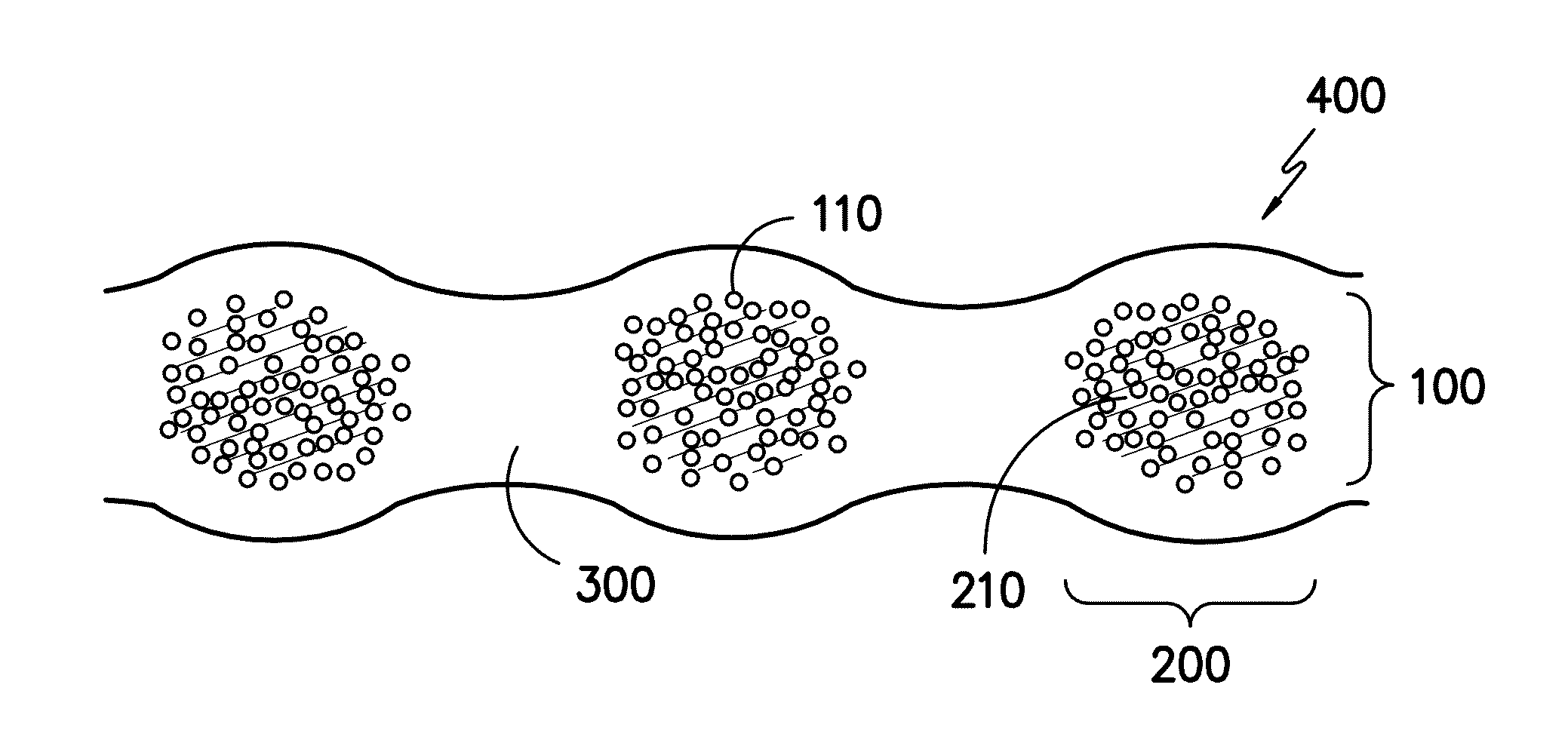
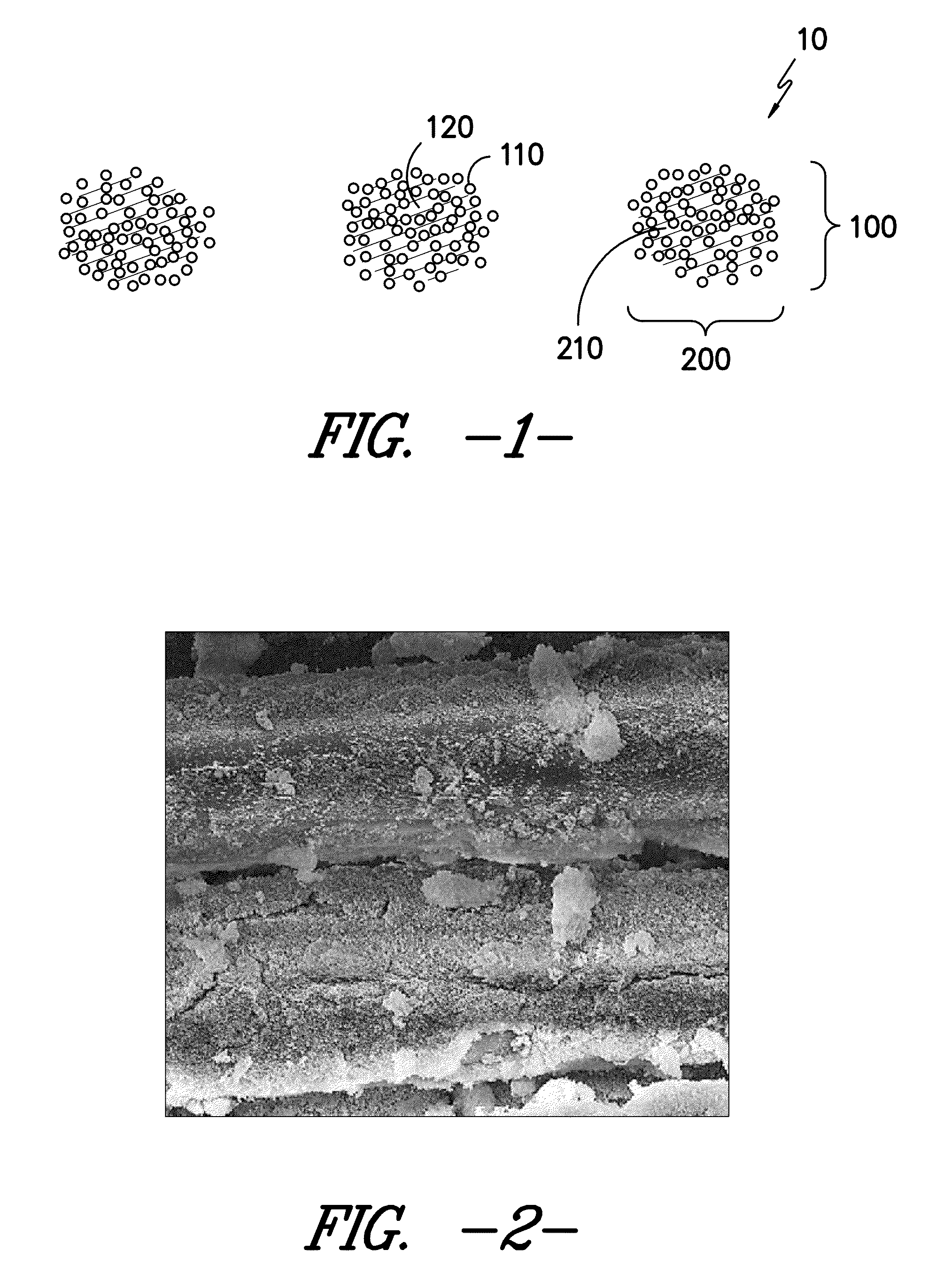
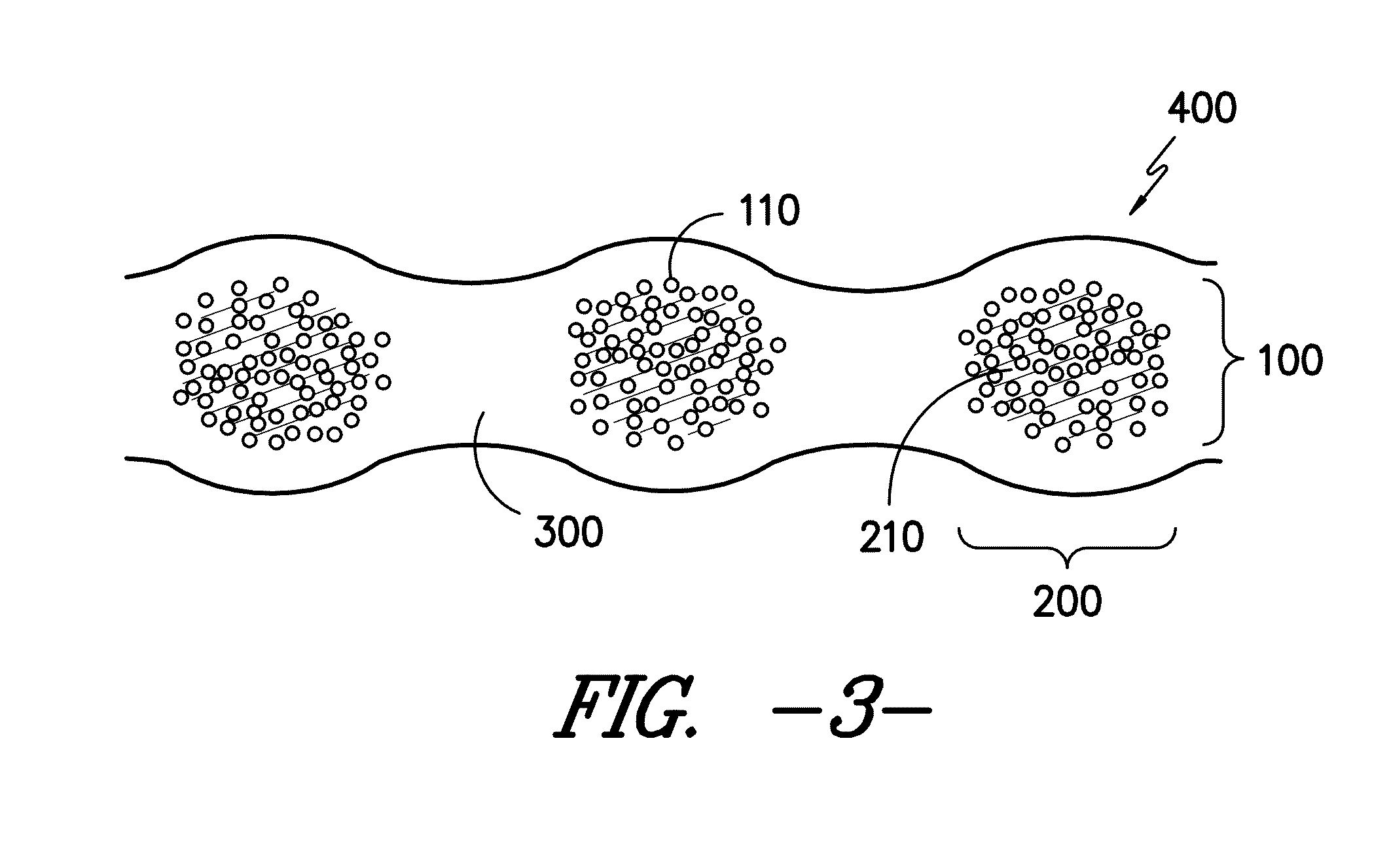
The process described in this patent results in a fiber bundle that has a coating of nanoparticles that form bonds with each other and with the fibers in the bundle. This creates a network of particles that increases the heat transfer and reduces the likelihood of fouling (when materials stick to surfaces). The process involves coating the fibers with a solution containing nanoparticles and then drying them to form the agglomerated network. The number of fibers with bonds can range from 10 to 100%, and the bonds can make up between 1% and 60% of the cross-sectional area of the bundle.

Problems solved by technology

In these material systems, fatigue damage is characterized by the initiation of damage at multiple sites, the growth of damage from these origin sites, and the interaction of the damage emanating from multiple origins.

Method used


Image

  • Process for forming an agglomerated particle cloud network coated fiber bundle
  • Process for forming an agglomerated particle cloud network coated fiber bundle
  • Process for forming an agglomerated particle cloud network coated fiber bundle

Examples


control example 1

[0114]An unsaturated polyester control sample was made using the sample layup procedure using the 090 fabric and the ±45 fabric. The stacked textiles were infused in a standard vacuum infusion apparatus at a vacuum of less than 50 mbar with 98.52% wt unsaturated polyester resin (Aropol Q67700 available from Ashland) and 1.48% wt methyl ethyl ketone peroxide (MEKP). The resin flow direction was along the 0° direction of the 090 fabric. The panel was cured at room temperature for more than 8 hours and further post cured at 80° C. for more than 4 hours. Fatigue testing of the unmodified glass reinforced unsaturated polyester composite at R=0.1 with a load of 1450 N / mm of specimen gage section width measured a lifetime of approximately 1×10⁴ cycles.

control example 2

[0115]An epoxy control sample was made using the sample layup procedure using the 090 fabric and the ±45 fabric. The stacked textiles were infused in a standard vacuum infusion apparatus at a vacuum of less than 50 mbar with 76.92% wt epoxy resin (EPIKOTE™ Resin MGS® RIMR 135 available from Momentive), 18.46% curing agent (EPIKURE™ Curing Agent MGS® RIMH 137 available from Momentive) and 4.62% wt curing agent (EPIKURE™ Curing Agent MGS® RIMH 134 available from Momentive). The resin flow direction was along the 0° direction of the 090 fabric. The panel was cured at room temperature more than 16 hours and further post cured at 80° C. for 24 hours. Fatigue testing of the unmodified glass reinforced epoxy resin composite at R=0.1 with a load of 1450 N / mm of specimen gage section width measured a lifetime of approximately 1×10⁵ cycles.

example 1

[0116]An agglomerated particle cloud network coated fiber bundle was formed by coating the 090 fabric with a dispersion of cationic fumed silica diluted to a 5% by weight concentration in water. The coating was conducted at room temperature and the textile was under tension in the machine direction and subjected to sonication and wrapping and travelling around 9 guide bars as shown in FIG. 17. The fabric bending angle after each guide bar was 21.95° to the face, 68.05° to the face, 176.15° to the face, 184.75° to the back, 184.70° to the face, 183.56° to the back, 183.56° to the face, 183.56° to the back, 97.07° to the face. After the guide bars, the textile traveled through a nip roller at a pressure of about 20,000 N / m and was dried at 150° C. for 3 minutes. This formed the agglomerated particle cloud network coated fiber bundle.

[0117]An SEM of the agglomerated particle cloud network coated fiber bundle is shown in FIG. 2 shows the presence of the agglomerated particle cloud netwo...


PUM

PropertyMeasurementUnit
porosityaaaaaaaaaa
average lengthaaaaaaaaaa
lengthaaaaaaaaaa

Abstract

A process of making an agglomerated particle cloud network coated fiber bundle containing forming a bundle of fibers, coating the bundle of fibers with a nanoparticle solution, and drying the solvent from the coated bundle of fibers at a temperature above room temperature forming an agglomerated particle cloud network coated fiber bundle comprising a plurality of agglomerated nanoparticles. The agglomerated nanoparticles are located in at least a portion of the void space in the bundle of fibers and form bridges between at least a portion of the adjacent fibers. Between about 10 and 100% by number of fibers contain bridges to one or more adjacent fibers within the agglomerated particle cloud network coated fiber bundle. The agglomerated nanoparticles form between about 1 and 60% of the effective cross-sectional area of the agglomerated particle cloud network coated fiber bundle.

Description

RELATED APPLICATIONS[0001]This application is related to the following application, which is incorporated by reference: Attorney docket number 6632, filed on Jul. 23, 2012 entitled, “Agglomerated Particle Cloud Network Coated Fiber Bundle”.FIELD OF THE INVENTION[0002]The present invention generally relates to the process of forming fiber bundles coated with an agglomerated particle cloud network and agglomerated particle cloud network composites.BACKGROUND[0003]The use of fiber reinforced composite materials in industry has grown as a way of delivering high strength components with lower weights. Wind turbines have gained increased attention as the quest for renewable energy sources continues. Composites are used extensively in the blades of wind turbines. The quest to generate more energy from wind power has prompted technology advances which allow for increased sizes of wind turbines and new designs of wind turbine components. As the physical size and presence of wind turbines inc...

Claims


Application Information

Patent Timeline
Patent Type & Authority Applications(United States)
IPC IPC(8): B05D3/02B32B1/00B05D7/00
CPCD06M11/45D06M11/79D06M23/08C08J5/005C08J5/06C08J2363/00C08J2367/06B29L2031/085B32B5/12C03C25/42C03C25/47Y10T428/2933Y02P70/50
Inventor JOHNSON, RYAN W.LI, XINWESSON, PAUL J.PUTHILLATH, PADMAKUMARWILSON, PHILIP T.
Owner MILLIKEN & CO
Learn More