
Drilling fluid using surfactant package

a technology of surfactant and drilling fluid, which is applied in the direction of drilling composition, chemistry apparatus and processes, etc., can solve the problems of high torque of the drill string in the horizontal section of the well, affecting the lubric affecting the lubricating performance of the drilling fluid, so as to improve the lubricating properties of the water-based drilling fluid, improve the lubricating properties, and minimize torque and drag problems

Inactive Publication Date: 2014-01-23
INTREVEP SA
View PDF2 Cites 49 Cited by
  • Summary
  • Abstract
  • Description
  • Claims
  • Application Information

AI Technical Summary

Benefits of technology

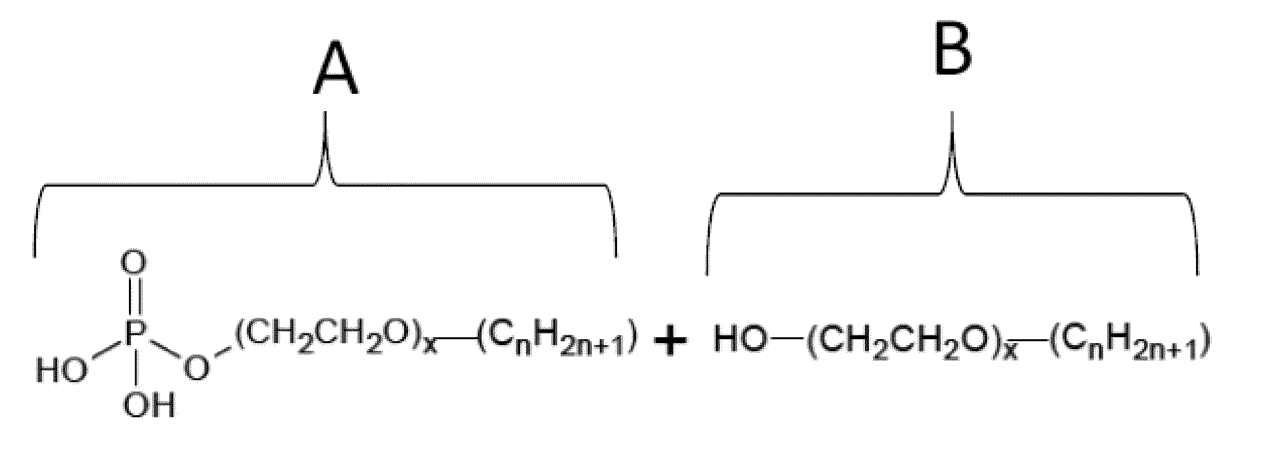
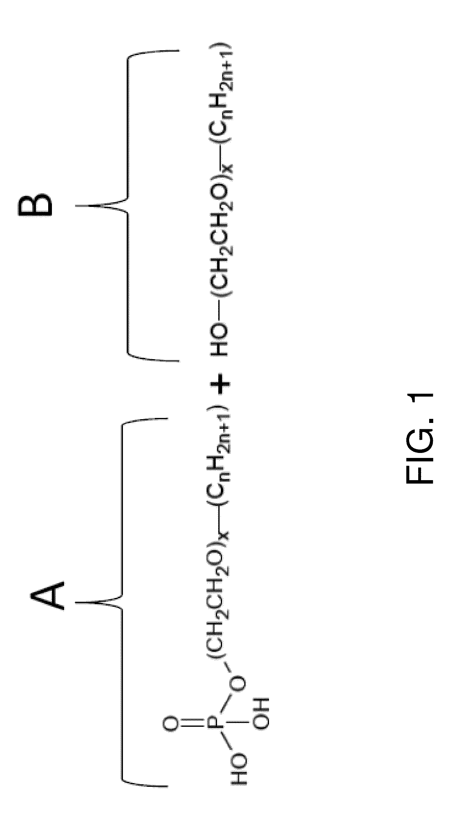
This patent presents a new additive for drilling fluid that includes a phosphate ester and non-ionic ethoxylated alcohol. This additive has excellent properties such as being a detergent, wetting agent, and lubricant. It helps to reduce torque and drag problems during well drilling operations, especially in cases where there are heavy oil and sand mixtures present. The patent also provides a new method for evaluating and selecting lubricant additives that can improve the lubricating properties of drilling fluid. Overall, this patent offers a solution for improving the performance of drilling fluid during well drilling operations.

Problems solved by technology

For instance, rig capacity can be compromised by excessive torque, and excessive drag can lead to problems sliding pipe or failure to set the casing or completion string.
The drill string in a horizontal section of the well suffers high torque due to the increased contact between the string and the horizontal wellbore.
The mixture of heavy oil with this unconsolidated sand results in the adherence of the oil and sand on the drill string and casing.
The accretion of drill cuttings over the drill string and the casing affects drilling operations by increasing the torque and drag.
The entire string can become stuck as a result of the increased drag, which can result in excessive operational costs to drill the hole.
Further, due to the unconsolidated nature of some heavy oil formations, it is usually necessary to line the horizontal wellbore by placing a slotted steel liner throughout the horizontal section.
However, none of these treatments has satisfactorily prevented the aforementioned operational difficulties.
In the Orinoco Oil Belt of Venezuela, when drilling extended horizontal sections of wells, problems related to torque and drag are frequently encountered.
These problems are produced by adhesion of heavy oil and sand over the drill string.
This accretion effect is the main cause of drilling process breakdowns and non-productive time.

Method used


Image

  • Drilling fluid using surfactant package
  • Drilling fluid using surfactant package
  • Drilling fluid using surfactant package

Examples


examples

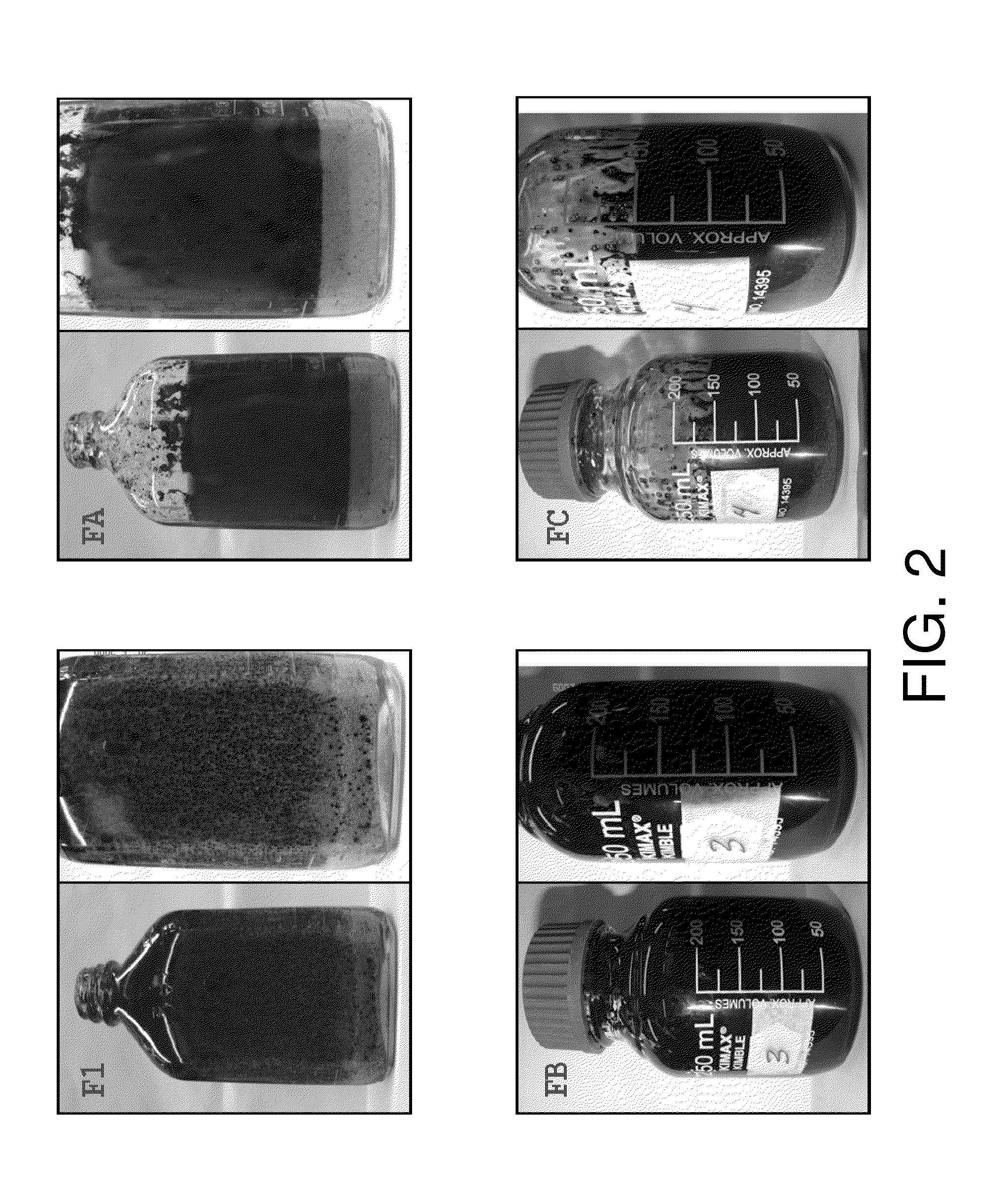
[0049]Water-based drilling fluids with different lubricant additives were prepared in order to test their properties for lubricity and liquid / liquid / solid (L / L / S) compatibility. Table 1 below shows characteristics of the fluids.

[0050]In order to evaluate the effect of each lubricant additive on lubricating properties of water-based drilling fluids, the lubricity coefficient was measured as the coefficient of friction (CF) at room temperature (22-23° C.), using a block-on-ring tribometer (OFITE Lubricity Tester, model 212 EP, OFI Testing Equipment, Inc.) The metal to metal lubricity testing device basically consists of a rotating steel ring against which a metal block can be compressed with variable loads using a torque wrench. Ring and block are immersed in the drilling fluid during the test and the friction force between both is measured. The following procedure was used: applying a constant load (W) 444.8 N by means of the torque arm, adjust the rotational speed of the ring at 60±...


PUM

PropertyMeasurementUnit
v/vaaaaaaaaaa
thicknessaaaaaaaaaa
coefficient of frictionaaaaaaaaaa

Abstract

A drilling fluid, comprising an aqueous continuous phase, and a surfactant system comprising a mixture of an ester phosphate and a non-ionic ethoxylated alcohol. The drilling fluid may also contain one or more of at least one salt, an alkaline material, a viscosifying agent, a starch or starch derivative, a bridging agent, a weighting material, and a diesel oil or non-aromatic oil.

Description

BACKGROUND OF THE INVENTION[0001]In the oil industry, there are drilling fluids of different nature, classified according to the external fluid phase as: water-based, oil-based, and pneumatic or gas-based systems. Basically, drilling fluids are composed of a base fluid (water or oil), a weighting material and other additives to control rheological properties, fluid losses and shale inhibition, among others. The type of drilling fluid selected for a drilling operation depends on the formation being drilled, the depth, the mechanical resistance and the wellbore's pressure. Regardless of the type of drilling fluid, its main functions are to: maintain hole integrity, transport rock cuttings from bottom hole to the surface, control formation pressure, and cool and lubricate the bottom hole assembly.[0002]The lubricity function is very important, due to the existence of frictional forces during all stages of well construction (drilling, completion and maintenance). Sources of frictional f...

Claims


Application Information

Patent Timeline
Patent Type & Authority Applications(United States)
IPC IPC(8): C09K8/06C09K8/28C09K8/10C09K8/08
CPCC09K8/12C09K8/28
Inventor GONZALEZ POCHE, JOSE MIGUELGODOY, FRANKLIN QUINTEROMARQUEZ SILVA, ROSA LINDAROSALES, SERGIOARELLANO VARELA, JESUS ENRIQUEOGALDE ARQUERO, HARRY WILSONPERNIA, DOMINGO
Owner INTREVEP SA
Learn More