Transoesophageal device using high intensity focused ultrasounds for cardiac thermal ablation

a technology of transoesophageal and ultrasound, applied in the field of transoesophageal devices, can solve the problems of thromboembolic risk, loss of atrial mechanical function, and not often used procedures, and achieve the effect of reducing the risk of thromboembolic complications

Inactive Publication Date: 2014-01-23
UNIV CLAUDE BERNARD LYON 1 +1
View PDF13 Cites 4 Cited by
  • Summary
  • Abstract
  • Description
  • Claims
  • Application Information

AI Technical Summary

Problems solved by technology

This arrhythmia is characterised by a disorderly and quick electrical activity, a loss of the atrial mechanical function and a thromboembolic risk.
However, this procedure is not often used because of its complexity.
Both of these methods are invasive.
Although the ideal design of a transducer, when attempting to sweep a focal zone in three dimensions, is a 2D phased array transducer (since

Method used


Image

  • Transoesophageal device using high intensity focused ultrasounds for cardiac thermal ablation
  • Transoesophageal device using high intensity focused ultrasounds for cardiac thermal ablation
  • Transoesophageal device using high intensity focused ultrasounds for cardiac thermal ablation

Examples


example 1

Feasibility of Transesophageal Cardiac Thermal Ablation

[0139]The feasibility of transesophageal cardiac thermal ablation using a 1D annular phased array transducer according to the present invention was investigated in computer simulation studies.

[0140]Simulation Configuration:

[0141]Numerical simulations of a treatment of AF by transesophageal HIFU have been performed with a model previously developed (Chavrier and al., 2000).

[0142]Generated pressure maps are calculated from Rayleigh's integral. Then temperature maps are determined using Pennes' Bio Heat Transfer Equation (1948). Finally, the thermal dose inside tissues (in minute equivalent to 43° C.) is calculated from the Sapareto and Dewey's formula (1984). Thereby a lesion is considered irreversible when the thermal dose is greater than or equal to 240 min i.e. 14400 s.

[0143]A realistic model of heart defined using the data of the Visible Human Project™ (VHP) (National Library of Medicine, Bethesda, Md.) was taken. Particularly...

example 2

Pressure Field Maps

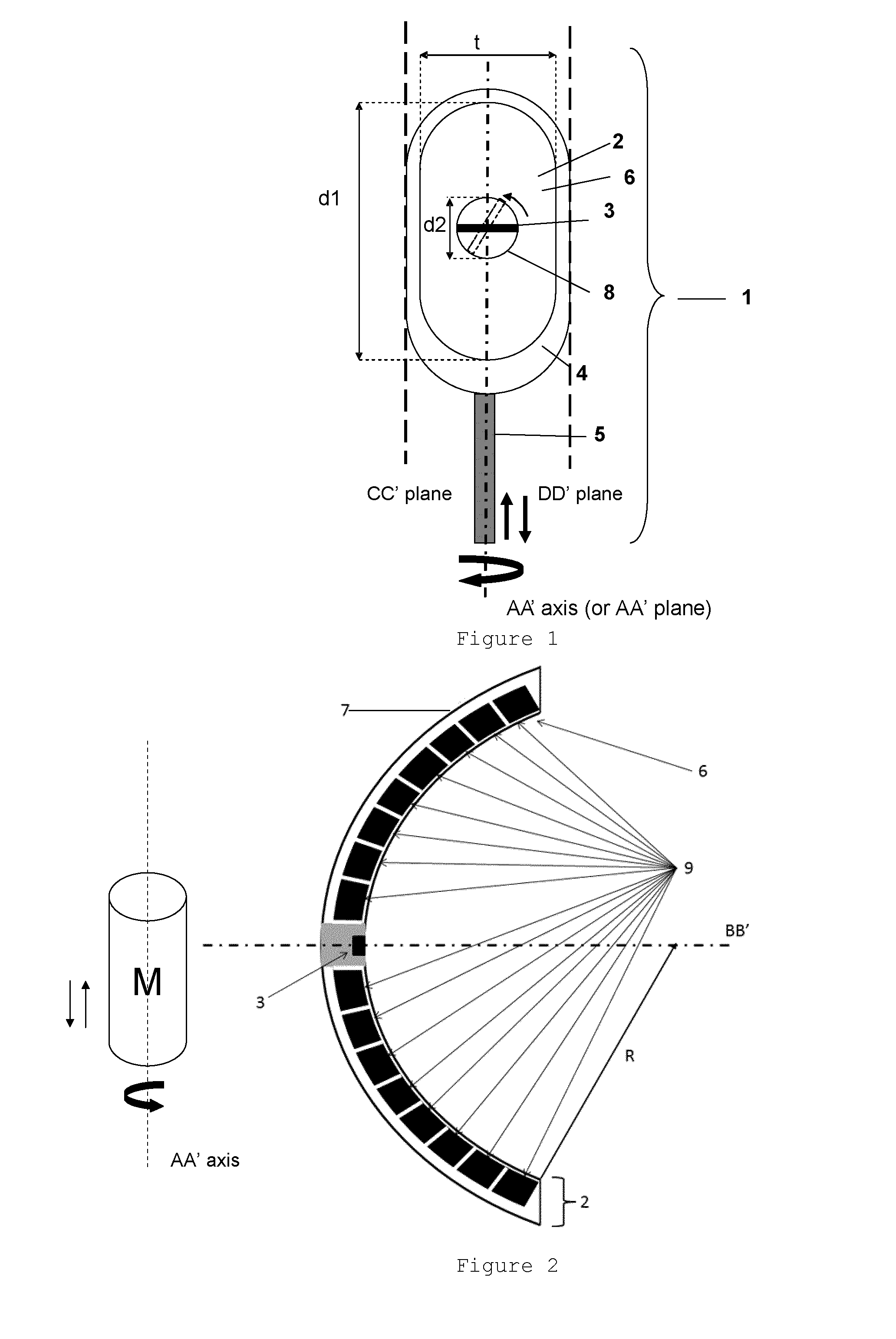
[0157]Based on the method of the example 1, simulations have been performed with the following characteristics:[0158]d1=30 mm,[0159]d2=12 mm,[0160]t=14 mm,[0161]R=40 mm,[0162]Frequency of the therapy transducer=3 MHz,[0163]Number of rings=8.

[0164]The conclusions of the example 1 are applicable to this geometry.

[0165]A prototype has been manufactured with these characteristics and pressure field maps according to different focusing (natural or electronic) have been performed.

[0166]These maps were obtained by motorized motion of a hydrophone (HGL-0200, Onda Corporation, Sunnyvale, Calif., USA) in a tank of degassed water.

[0167]Two planes have been acquired. XZ plane is the AA′ plane and YZ plane is the BB′ plane.

[0168]First, pressure field maps have been performed at 40 mm focusing (FIG. 7). This focusing is due to the transducer spherical shape. So this is the natural configuration. It offers the largest focal spot for the minimum number of secondary lobes.

[0169]Th...

example 3

Multiplane Imaging Transducer

[0176]This example presents the point of having a multiplane imaging transducer instead of a biplane or a monoplane transducer. Here, CT images are used instead of ultrasound images.

[0177]FIG. 11a illustrates a cross-section of the left atrium upper part where a lesion has to be performed. The probe (P), the target (T) to treat and the acoustic axis BB′ are represented on this figure. No particular obstacle for ultrasound propagation seems to be visible.

[0178]FIG. 11b illustrates the same cross-section but also the AA′ plane which can be visible with a biplane transducer. In this AA′ plane trachea can be located and seems to be at a sufficient distance (d) from T.

[0179]FIG. 11c shows the two planes but also the 3D trachea representation which has been obtained by segmentation of the CT images. The minimum distance between the trachea area (TA) and T cannot be measured with a biplane transducer without a rotation of the entire probe around the AA′ axis.

[0...


PUM


Abstract

The present invention relates to a probe that comprises a piezoelectric therapy transducer having an acoustic axis BB′, and an imaging transducer having an imaging plane, in which the therapy transducer and imaging transducer are mounted in a head which is itself connected to a guide. More particularly, the therapy transducer is in a form of a truncated cup and has a spherical concave front face for emitting ultrasonic waves focused on a focal point, a rear surface and the therapy transducer is truncated alone two parallel lanes such that a length d1, a width t and a longitudinal direction are provided; the therapy transducer is a 1D annular phased array transducer and the imaging transducer is a multiplane transducer having a rotation axis corresponding to the acoustic axis of the therapy transducer whereby the focal point of the therapy transducer is comprised in the imaging plane of the imaging transducer, said imaging transducer being fixed to the therapy transducer

Description

TECHNICAL FIELD[0001]The present invention relates to a transoesophageal device, and also to a system comprising said transoesophageal device and constituting an application for treating atrial fibrillation.BACKGROUND OF THE INVENTION[0002]Atrial fibrillation is the most frequent cardiac arrhythmia. As an example, in 2008, it affected more than 750.000 people in France and should affect near to two million by 2050, in majority elderly people (65-80 years old).[0003]Atrial fibrillation would be responsible of 15% of cerebrovascular accidents in France.[0004]This arrhythmia is characterised by a disorderly and quick electrical activity, a loss of the atrial mechanical function and a thromboembolic risk. The resulting quick and irregular ventricular activity can be responsible of cardiac insufficiency.[0005]This arrhythmia is caused by anatomical or electrophysiological abnormalities of the myocardium.[0006]A successful treatment for the cardiac arrhythmia often requires blocking or mo...

Claims


Application Information

Patent Timeline
IPC IPC(8): A61B5/00A61B8/08A61B17/32
CPCA61B5/4836A61B17/320068A61B8/48A61B2018/00023A61N7/022A61N2007/0078A61N2007/0082A61N2007/0091A61N2007/0095A61B2090/3784A61B5/0036
Inventor CHAPELON, JEAN-YVESCONSTANCIEL, ELODIELAFON, CYRIL
Owner UNIV CLAUDE BERNARD LYON 1
Why Eureka
Try Eureka