
Method for fatigue assessment of rolling bearing

a technology of rolling bearings and fatigue assessment, applied in the direction of mechanical equipment, instruments, force measurement by measuring optical property variation, etc., to achieve the effect of fast prediction

Inactive Publication Date: 2014-01-30
AB SKF
View PDF4 Cites 4 Cited by
  • Summary
  • Abstract
  • Description
  • Claims
  • Application Information

AI Technical Summary

Benefits of technology

The present invention provides an improved method to evaluate the resistance of steel to rolling contact fatigue in rolling bearings. This method allows for a more efficient, cost-effective way to predict the fatigue limit for a combination of specified bearing properties, such as material and heat treatment. The method also facilitates the prediction and definition of the relationship between contact stress and sub-surface initiated fatigue. The apparatus arrangement according to the present invention improves evaluation and assessment of the resistance of steel to rolling contact fatigue in rolling bearings.

Problems solved by technology

Hence, compared to known test methods of prior art which are indirect and do not provide a direct prediction of rolling contact fatigue limit, the present method facilitates and expedites a prediction and definition of the relationship between contact stress and sub-surface initiated fatigue.

Method used


Image

  • Method for fatigue assessment of rolling bearing
  • Method for fatigue assessment of rolling bearing
  • Method for fatigue assessment of rolling bearing

Examples


Embodiment Construction

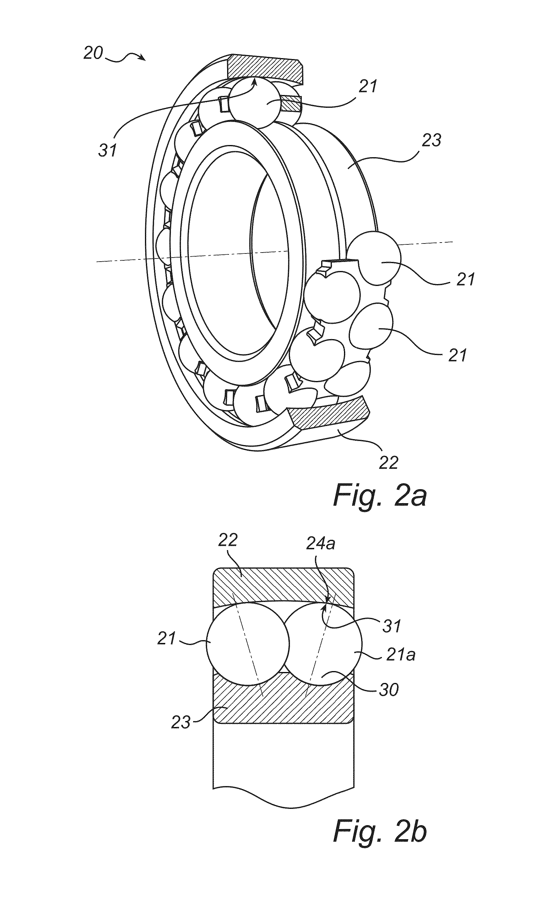
[0038]In the drawings, similar, or equal elements are referred to by equal reference numerals. The drawings are merely schematic representations, not true to scale and should not be considered as limiting the scope of the invention.

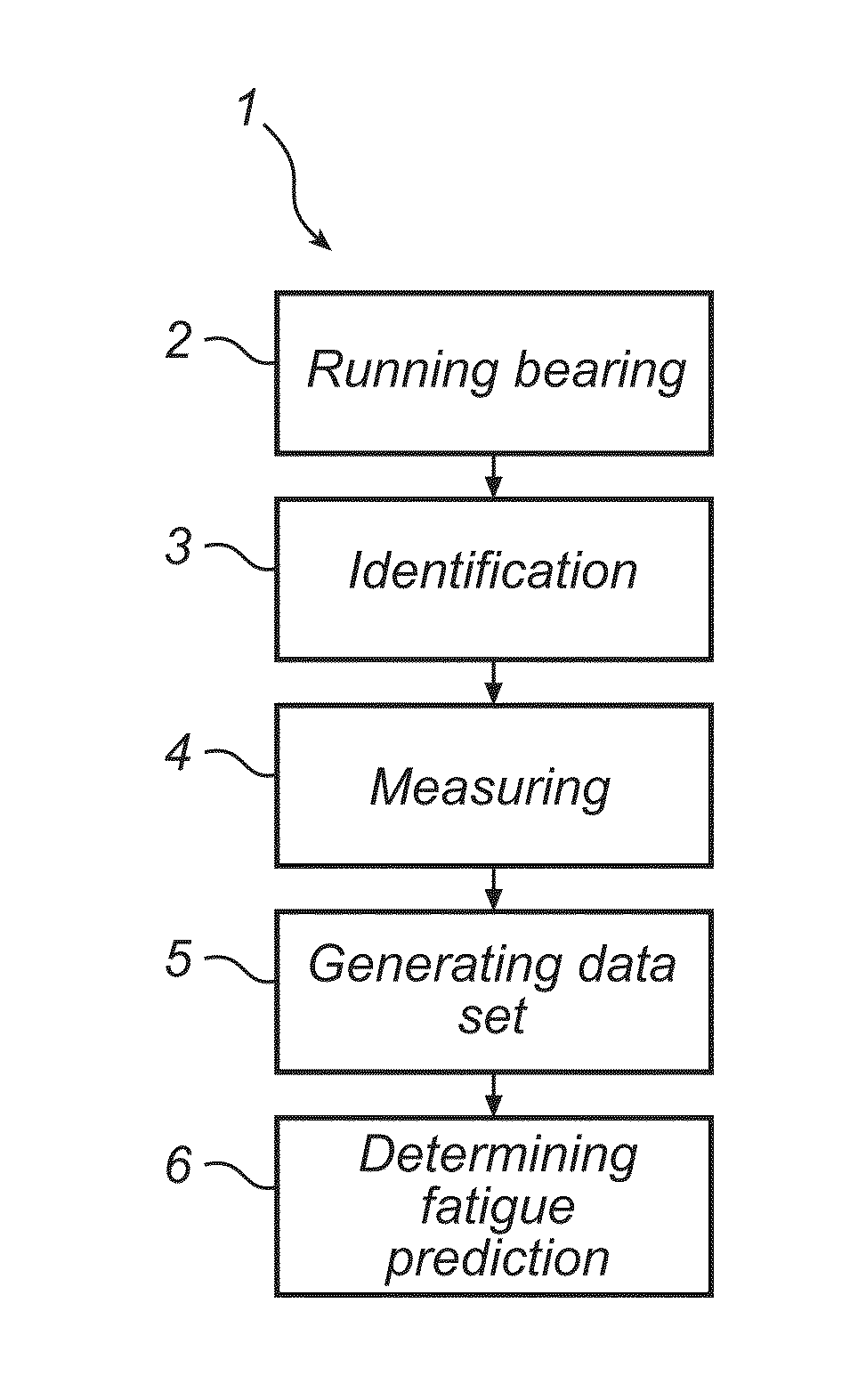
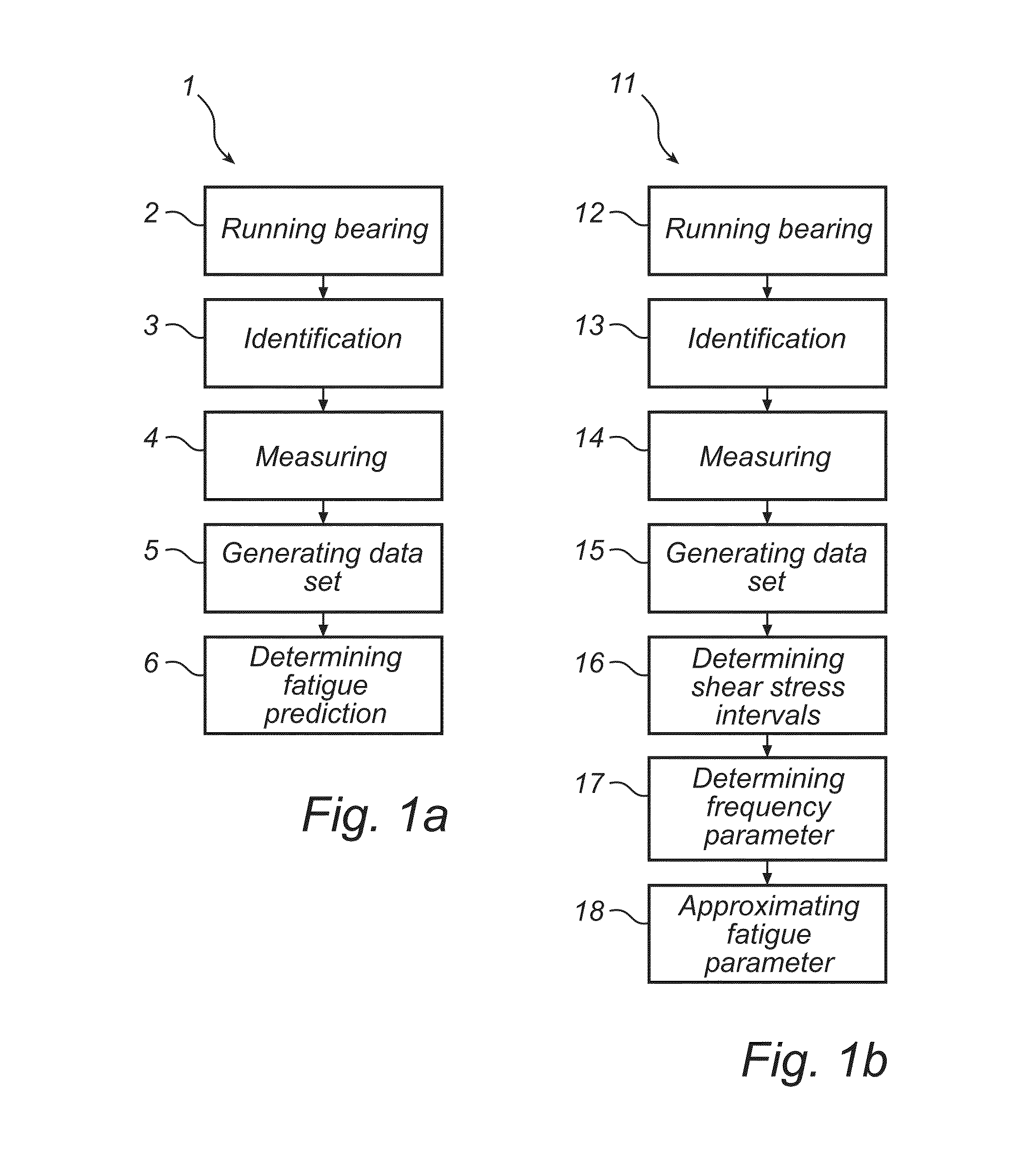
[0039]In FIG. 1a-b two different method embodiments 1 and 11 according to the present invention are illustrated in schematic flow charts. With reference to FIG. 1a, in an initial running bearing step 2, a test bearing is run in a test rig, such as an SKF R-2 test machine, wherein the test bearing is subject to a mechanical load which generates sub-surface transformations in the raceway contact zone. The contact zone is formed of the three dimensional volume of the raceway material which is subject to internal stress and shear stress conditions generated and initiated at the e.g. the point shaped rolling contact area between a ball shaped rolling element and the raceway. Typically, the test bearing is run until the occurrence of spalling or sub-surface ini...


PUM


Abstract

The present invention related to a method, and an apparatus arrangement, for determining a fatigue limit for rolling contact initiated fatigue of a rolling bearing. The method comprises running a rolling bearing while being exerted to a load which generates sub-surface transformations in a rolling element contact zone of the outer or inner ring. Furthermore a set of sub-surface transformations in the contact zone along a raceway portion of the rolling bearing is identified and measured and used for generation of a parameter data set, wherein a fatigue parameter value representative of a predicted fatigue limit for the rolling bearing is determined based on the generated data set of sub-surface transformations.

Description

FIELD OF THE INVENTION[0001]The present invention relates to a method, or a test method, for determining a fatigue limit for rolling contact initiated fatigue of a rolling bearing. The method comprises running a rolling bearing comprising a plurality of rolling elements arranged between an outer and an inner ring, while the rolling bearing is exerted to a load which generates sub-surface transformations in a rolling element contact zone of the outer or inner ring.[0002]The present invention further relates to an apparatus arrangement for testing a rolling bearing for the purpose of determining a fatigue limit for rolling contact initiated fatigue, wherein the apparatus arrangement comprises a test rig for running a rolling bearing which is arranged to exert a load on the rolling bearing for generation of sub-surface transformations in a rolling element contact zone of the outer or inner ring of the rolling bearing.[0003]The method and apparatus arrangement according to the present i...

Claims


Application Information

Patent Timeline
IPC IPC(8): G01N3/24
CPCG01N3/24G01M13/04G01M13/045F16C19/522F16C33/416F16C23/086F16C33/40F16C19/52F16C19/183
Inventor LUND, THORERYDEN, KARIN
Owner AB SKF
Learn More