Energy generation system

a technology of energy generation and solar panels, which is applied in the field of solar panel mounting systems, can solve the problems of not being able to sustain the large torsional load, the actual construction of the system is subject to intense scrutiny, and the wind load can be present in a typical tracking pv system, so as to prevent the shifting of the bearing elements over a long time of use, high density, and the effect of enduring high loads

a technology of energy generation and solar panels, which is applied in the field of solar panel mounting systems, can solve the problems of not being able to sustain the large torsional load, the actual construction of the system is subject to intense scrutiny, and the wind load can be present in a typical tracking pv system, so as to prevent the shifting of the bearing elements over a long time of use, high density, and the effect of enduring high loads

US20140026940A1Inactive Publication Date: 2014-01-30PV HARDWARE

Image

  • Energy generation system
  • Energy generation system
  • Energy generation system

Examples


Embodiment Construction

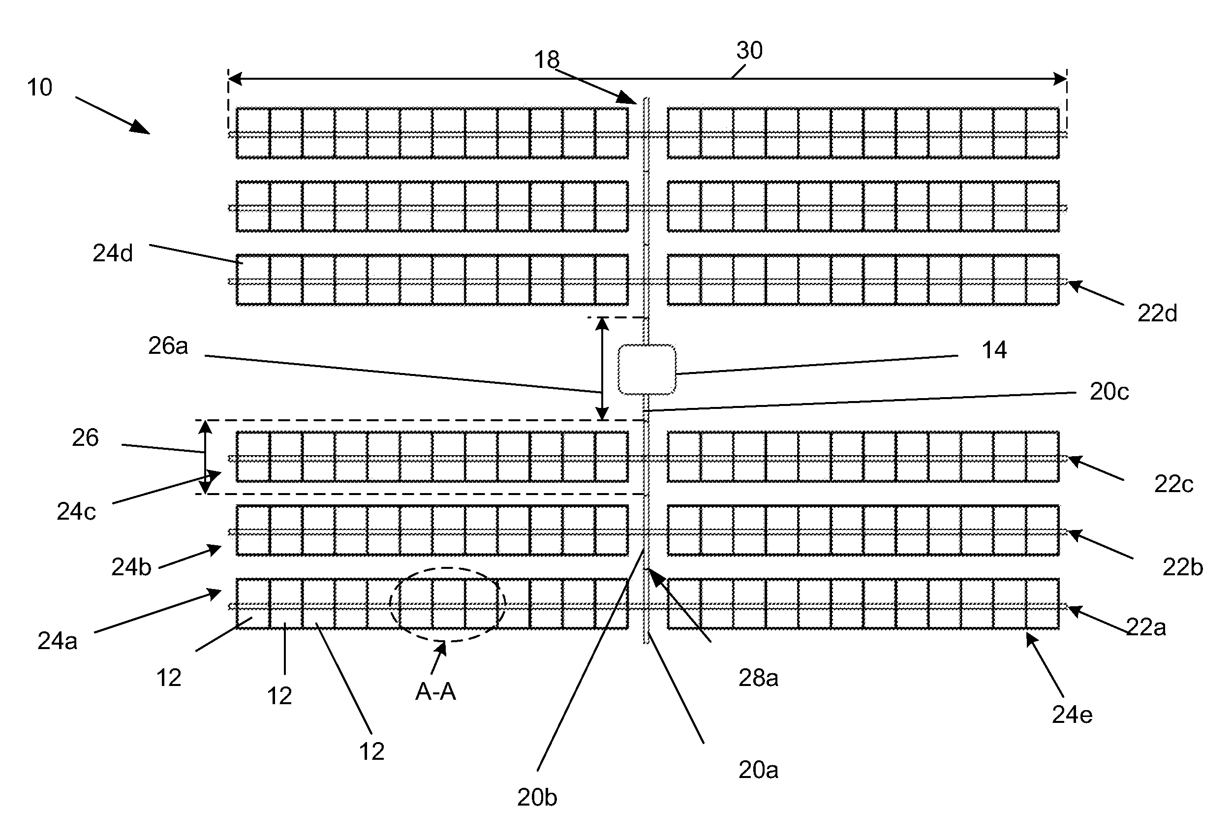
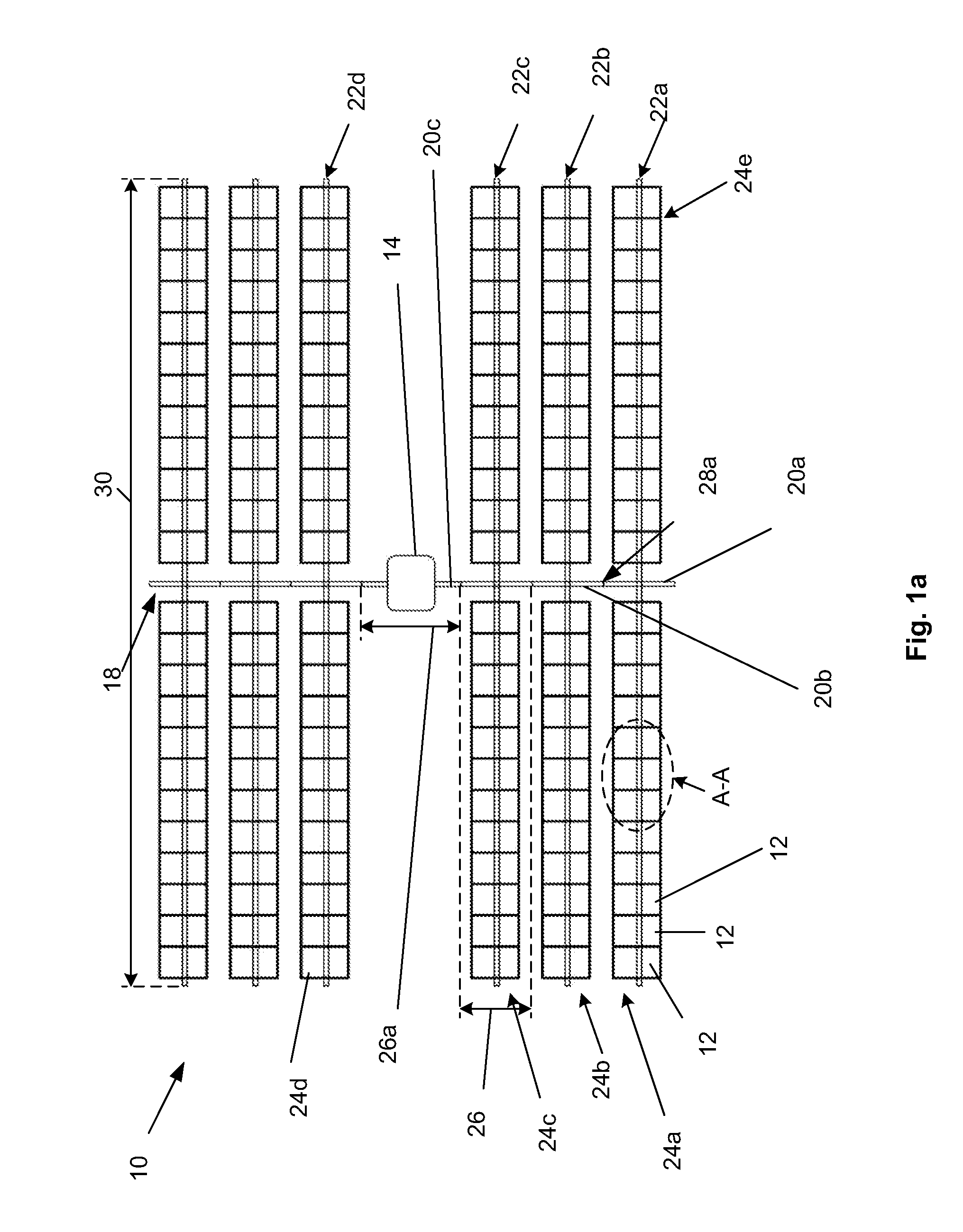
[0035]FIG. 1 illustrates that a photovoltaic (PV) or solar panel array 10 can have one or more PV modules or panels 12. Each PV module 12 can be a framed power producing PV element, such as a framed collection of solar cells. A number of the PV modules 12, for example from about 20 to about 50, more narrowly from about 24 to about 44, for example about 24 or 44, can be oriented into rows or lines. The panels 12 can be, for example, all-framed crystalline panels. The array 10 can produce, for example, from about 250 kW to about 50 MW of electrical power from the panels 12. One array 10 could produce less than 250 kw, but typically 330-500 kW per array, or “block”.

[0036]The array 10 can have a drive motor, such as a linear actuator 14, for example a ram screw. The linear actuator 14 can be located in the center of the array 10, as shown, at a terminal end of the array 10, or elsewhere within the array 10. The actuator 14 can be, for example, about a 1.5 hp to about a 5 hp, for example...


PUM

PropertyMeasurementUnit
Lengthaaaaaaaaaa
Molecular weightaaaaaaaaaa

Abstract

A system is disclosed that can include an array of solar panels. The array can be arranged into rows of linearly organized modules. The modules can be tilted by a linear actuator attached to a linkage. The tilting can be controlled to maintain a perpendicular orientation between the face of the solar panels (modules) and the direction to the sun.

Description

BACKGROUND[0001]1. Field of the Invention[0002]A system for mounting photovoltaic solar panels and more particularly, to a mounting support system that drives a number of rows of solar panels to track the motion of the sun relative to the earth is disclosed. More particularly, systems are disclosed that are directed to reliability and ease of installation of the tracker arrangement for tilting a group or array of rows of solar panels. The systems can include or be used with solar collectors in which the panels are arrays of photovoltaic cells for generation of electrical power, though the system can also include or be used with arrangements for solar energy concentration, for example.[0003]2. Description of the Related Art[0004]Solar photovoltaic (PV) cells convert light directly into electricity. By utilizing the most abundant, renewable energy available on the planet, namely the sun's rays, PV cells can provide a non-polluting source of electrical energy. As global energy consumpt...

Claims


Application Information

Patent Timeline
30 Jan 2014
Publication
US20140026940A1
IPC
H01L31/052; H01L31/18
CPC
H01L31/18; H01L31/0522; Y02E10/50; H02S20/00; Y02E10/47; F24S2030/19; F24S30/425; F24S2030/15
Inventors
ALONSO SALMERON, JUAN P.; ARKIPOFF, IVAN