Holding structure for simultaneously holding a plurality of containers for medical, pharmaceutical or cosmetic applications and transport or packaging container with holding structure

Inactive Publication Date: 2014-01-30
SCHOTT AG
View PDF11 Cites 37 Cited by
  • Summary
  • Abstract
  • Description
  • Claims
  • Application Information

AI Technical Summary

Benefits of technology

[0025]According to a further embodiment, at least a major part of the bottoms or bottom ends of the containers is freely accessible from the bottom side of the supporting structure. Preferably, these vial bottoms are not covered by any supporting structures or the like. According to further embodiments, however, a supporting web or the like may be provided at the bottom ends of the openings or receptacles of the supporting structure for supporting the bottoms or bottom ends of the containers. Thus, an adjusting device, such as an adjustment finger, can act on the bottoms or bottom ends of the containers from the bottom side of the supporting structure in order to displace them in axial direction or rotate them

Problems solved by technology

This limits the speed of further processing that can be achieved.
Particularly in the case of the isolation of containers by means of cell wheels or the like, it always happens that individual containers abut uncontrolled, leading to an undesired abrasion and subsequently to a contamination of the interior of the container or of the processing station as well as to an impairment of the outer appearance of the containers, which is undesirable.
Upon evacuation and the subsequent opening of the plastic tube, however, the medication containers may slip sideways, which increases the automation efforts required for processing further the medication containers.
In addition, the medication containers may still collide uncontrolled after opening of the plastic tube, resulting in the aforementioned disadvantages.
A batch-wise further processing of t

Method used


Image

  • Holding structure for simultaneously holding a plurality of containers for medical, pharmaceutical or cosmetic applications and transport or packaging container with holding structure
  • Holding structure for simultaneously holding a plurality of containers for medical, pharmaceutical or cosmetic applications and transport or packaging container with holding structure
  • Holding structure for simultaneously holding a plurality of containers for medical, pharmaceutical or cosmetic applications and transport or packaging container with holding structure

Examples


Embodiment Construction

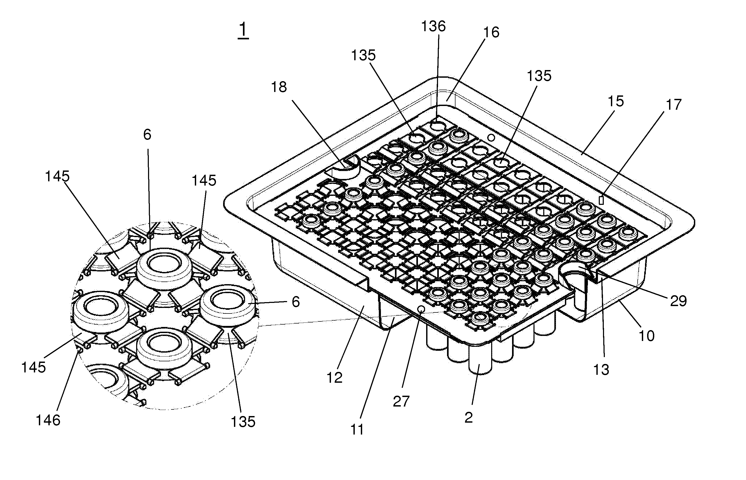
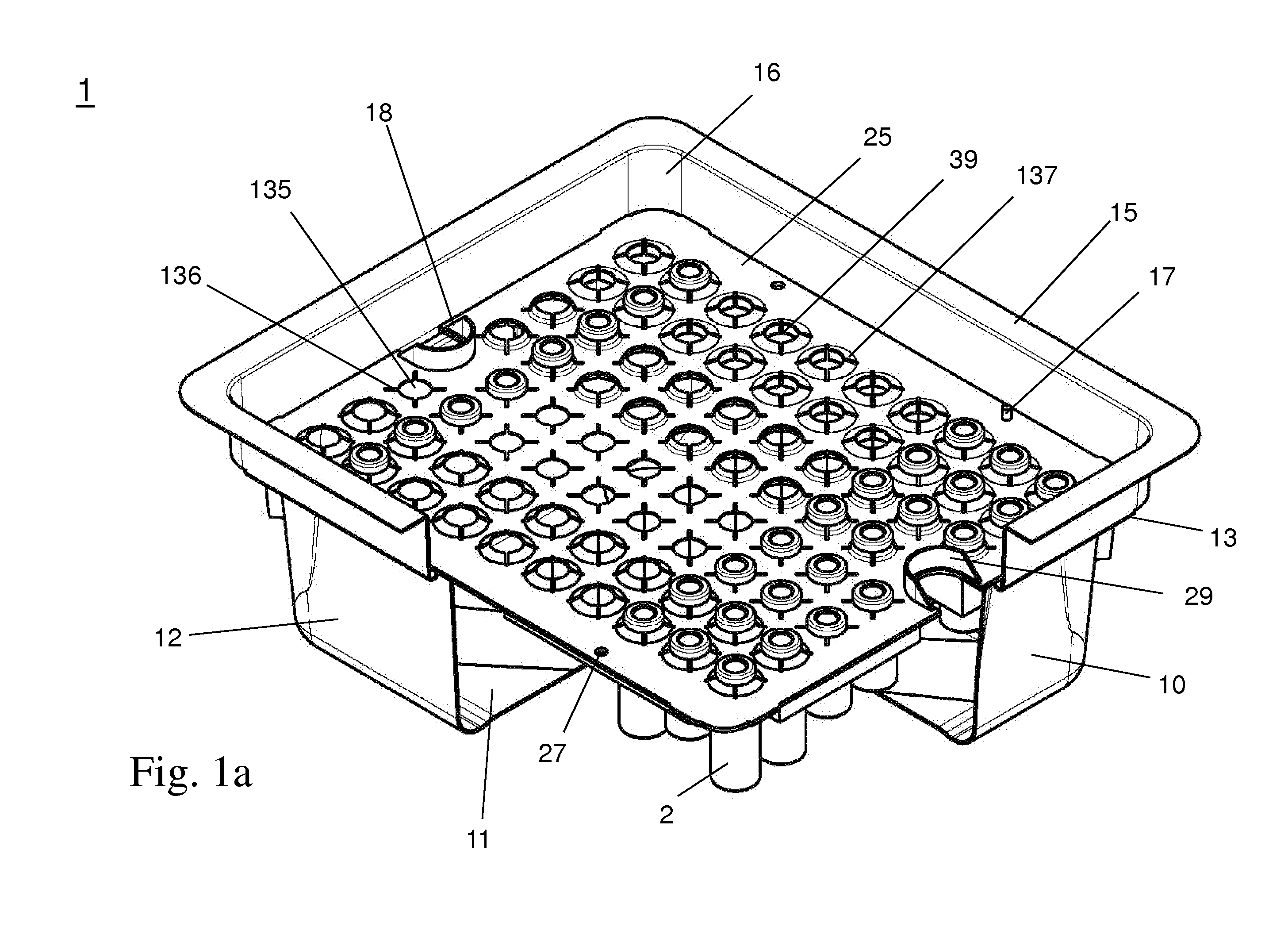
[0047]A supporting structure (in the prior art often referred to also as “nest”) as well as a transport and packaging container (in the prior art often referred to also as “tub”) that receives such a supporting structure used in the present invention, as described below, are used for concurrently supporting a plurality of containers for storage of substances for cosmetic, medical or pharmaceutical applications, in a regular arrangement, in particular in a matrix array at regular distances of the containers to each other, along two different directions in space, preferably along two mutually orthogonal spatial directions or regular rows, which are displaced relative to each other.

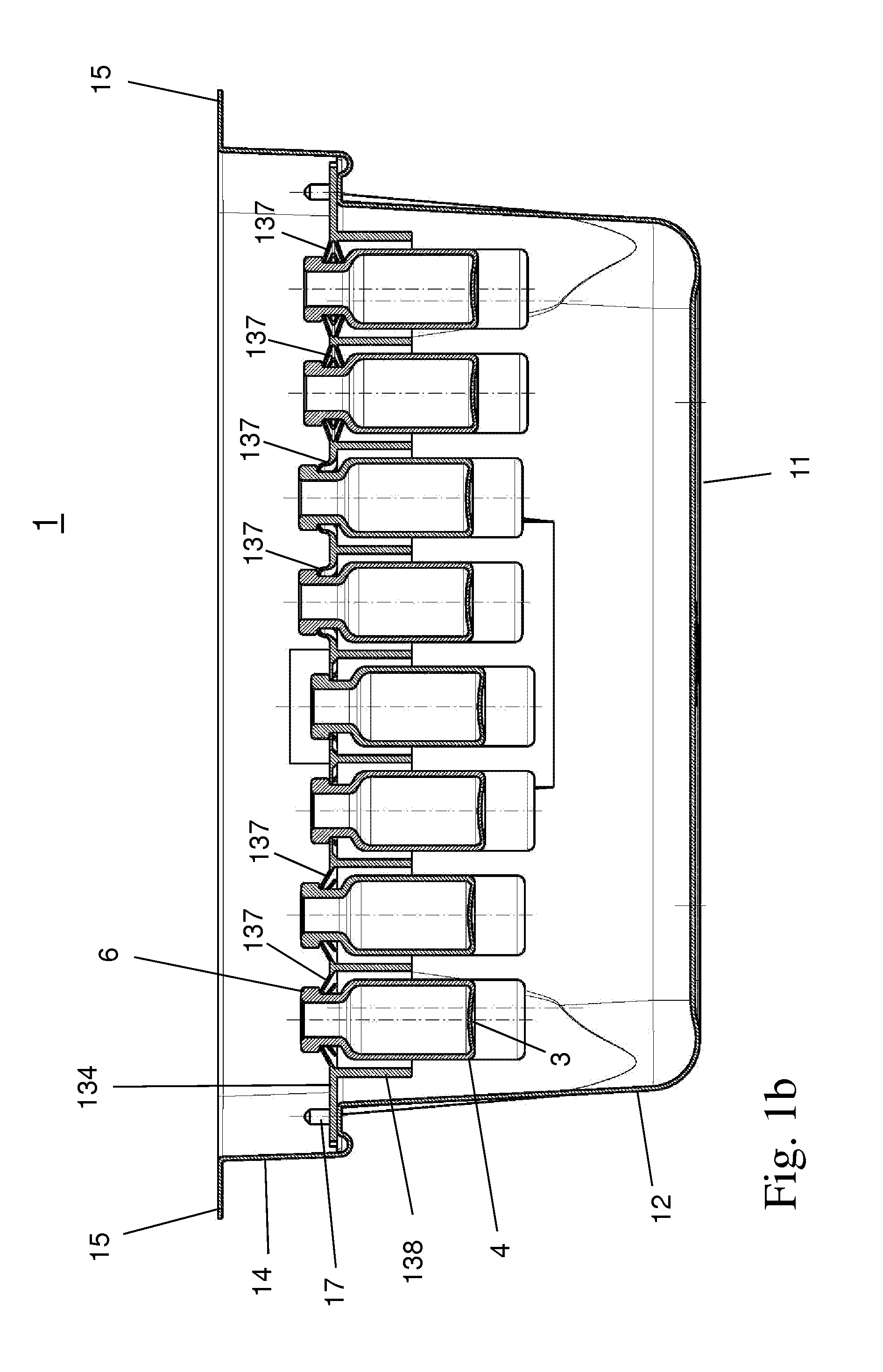
[0048]An example of such medication containers in the form of vials (English: vial) is shown schematically in FIG. 4c in a longitudinal section and have a cylindrical basic shape, having a cylindrical side wall having—within tolerances—a constant inner and outer diameter, which protrude vertically from a fla...


PUM


Abstract

A supporting structure is provided that concurrently supports a plurality of containers for substances for medical, pharmaceutical or cosmetic applications. The supporting structure includes a planar supporting base having a plurality of openings, which are disposed in a regular array configuration, and an associated holding device that supports the plurality of containers in a positive-fit manner at the supporting base. The holding device protrudes from a bottom side of the supporting base and is configured to support the plurality of containers in the positive-lit manner at their upper rim. Additionally, receptacles are provided on an upper side of the supporting base opposite to the bottom side for accommodating containers at the upper side of the supporting base.

Description

[0001]The present application claims priority from German Patent Application No. 10 2012 103 898.8 “Supporting structure for concurrently supporting a plurality of medical or pharmaceutical containers and transport or packaging container with the same”, filed on 3 May 2012, and from U.S. Patent Application Ser. No. 61 / 642,154 “Support structure for simultaneously holding a plurality of medical or pharmaceutical containers and transport containers or packaging container comprising such a support structure”, filed on 3 May 2012, the entire contents of which are hereby incorporated by way of reference.FIELD OF THE INVENTION[0002]The present invention relates in general to the concurrent holding or supporting of a plurality of containers for the storage of substances for medical, pharmaceutical or cosmetic applications, in particular of flasks (vials), and more particularly to concurrently supporting a plurality of containers in a supporting structure in such a manner that they may be p...

Claims


Application Information

Patent Timeline
IPC IPC(8): A61J1/14
CPCA61J1/14B01L9/06B01L2200/023A61M5/008
Inventor PAWLOWSKI, EDGARWISSNER, KAICOULON, JOELLOVIS, RALPHHEITER, CARMEN
Owner SCHOTT AG
Why Eureka
Try Eureka