Multiregion heated eye shield

a multi-region, eye shield technology, applied in underwater equipment, instruments, transportation and packaging, etc., can solve the problems of inability to customize the heating method, inability to teach the method of employing a thin-film heating system, and inability to prevent fogging, so as to prevent fogging, prevent hot spots on the eye shield, and eliminate undesirable hot spots

Active Publication Date: 2014-01-30
TEMPEST OPTICS LLC
View PDF5 Cites 21 Cited by
  • Summary
  • Abstract
  • Description
  • Claims
  • Application Information

AI Technical Summary

Benefits of technology

[0025]The eye shield of the invention provides a unique fog-prevention eye shield for use in connection with ski goggles, dive masks, motorcycle helmet visors or snowmobile helmet visors, and the like. Further the eye shield in accordance with the invention provides a unique fog-prevention eye shield for use in medical, high-tech, testing or other working environments where fogging of a visor or eye shield may become a problem. The elimination of undesirable hot spots on the eye shield is accomplished with the invention in that each region may be designed to an appropriate size and shape that yields a power density that is appropriate for the size of the region being heated. And while the invention enables prevention of fogging while also preventing hot spots on the eye shield without the need for a pulse-width modulated (PWM) system as described in co-pending U.S. patent application Ser. No. 13/397,691, Publication No. US2013/0212765A1 to Cornelius, it may also be used in connection with such a PWM system if so desired for other reasons. Thus, the invention accomplishes heating of the eye shield, and thus prevention of fogging while also preventing hot spots on the eye shield in that the balancing of the heating of the eye shield, or conversely customized zone heating of the eye shield, is determined by the eye shield itself and at the time of design and manufacture. This makes provision of the eye shield, and the resulting goggle, mask or other eye shield, more cost effective to produce and more functionally efficient in preventing fogging and hot spots on the eye shield, since less complicated and less expensive electronics are able to be used to produce the eye shield and hence the resulting eye wear.
[0026]The foregoing aspects of the invention provide an eye shield that is adapted for being heated in an electrical circuit to raise the temperature of the inner surface of the eye shield above the dew point in order to prevent fogging, without creating undesirable hot spots in portions of the eye shield, e.g., over the bridge of the nose, where a unitary evenly-applied heating material would produce too much power for the region causing it to overheat. Further, with the use of PWM to maximize efficiency of the system as disclosed in co-pending U.S. patent application Ser. No. 13/397,691, Publication No. US2013/0212765A1, to Cornelius, the foregoing benefits and properties are able to be accomplished by powering the eye s...

Problems solved by technology

Fogging that impairs vision is a common problem with such goggles, dive masks and eye-protecting shields.
There have been various conductive apparatus devised for preventing condensation build-up on eye-shields for eye-protecting shields, and while a rectangular eye shield with a thin-film heater may have been evenly heated across the eye-shield, but none have taught a method for employing a thin-film heating system in an eye shield that enables even heating of the eye shield, or alternatively customized heating of the eye shield according to a lens heating profile, according to the configuration and application of the thin-film heating material to the eye shield.
The purpose of these conductive apparatus has been simply to provide an eye shield that may be maintained free of condensation so that the user would be able to enjoy unobstructed vision during viewing activities, and as such they have been subject to problems of creating hot spots on irregular-shaped lenses and have not provided for customizable heating of lens.
However, Reuber et al. does not disclose even heating of a lens, or alternatively customized heating of the lens in accordance with a heating profile, by employing a certain configuration of thin-filmed heating material on the lens.
Thus, a problem with sport goggles which have employed electrical heating is that of uneven heating over the entire surface of an irregular-shaped eye shield.
Lebel et al. would be susceptible to hot spots, and using such devices in limited battery-powered applications has unduly discharged the battery.
For example, where the terminals are on either side of the lens in a resistive wiring app...

Method used


Image

  • Multiregion heated eye shield
  • Multiregion heated eye shield
  • Multiregion heated eye shield

Examples


Embodiment Construction

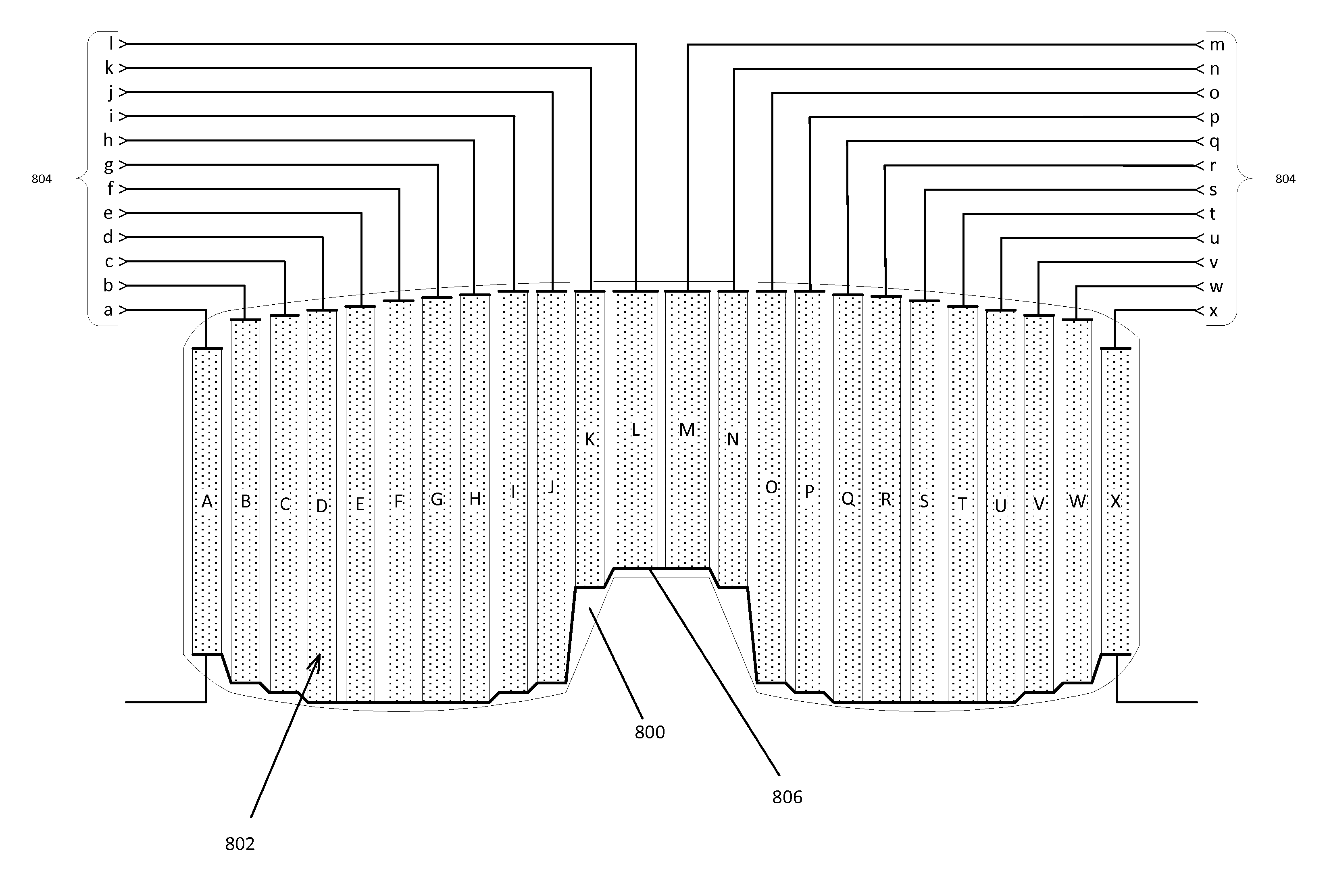
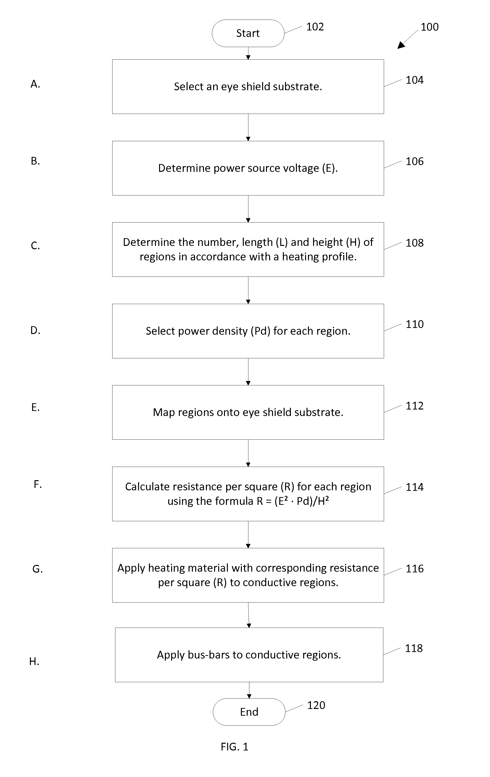
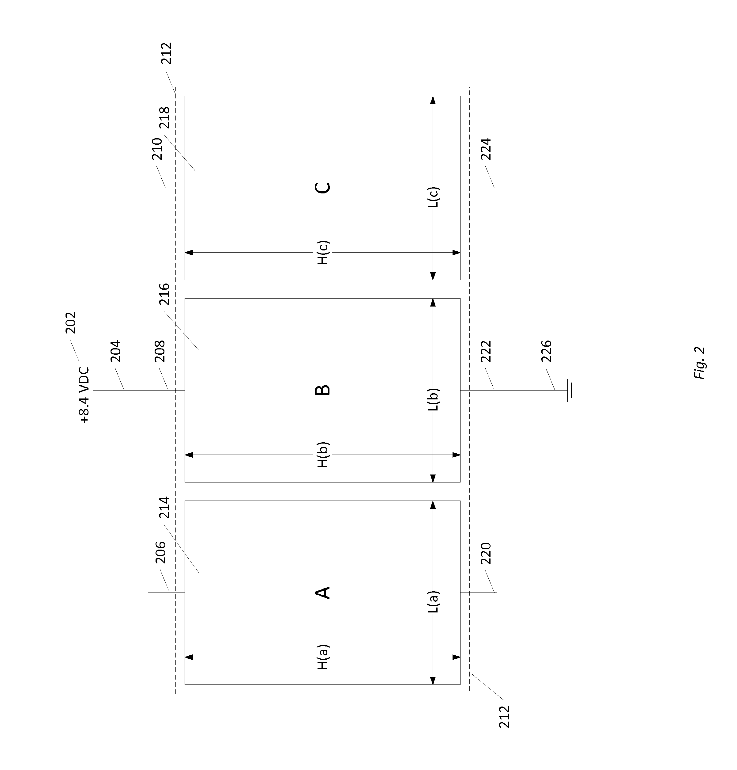
[0043]Referring to FIG. 1, a method 100 starting at origination location 102 for adapting an optically-transparent eye shield for use in an electrical circuit to prevent fogging of the eye shield while preventing hot spots on the eye shield is disclosed. The method 100 comprises the following steps after starting at 102: selecting a nonconductive substrate at 104 defining an optically-transparent eye shield and an outer periphery of the eye shield; determining the power source voltage at 106, which is preferably a dc battery voltage source (e.g., 8.4 VDC which is the output of two 4.2 VDC, fully-charged, lithium-ion cells), but which may also be an output from a PWM driver; heating profile for defining a heating pattern within the outer periphery of the eye shield; determining at 108 the number of a plurality of regions and the size of each region (whether electrically-isolated or contiguous) in accordance with a heating profile; selecting at 110 a desired power density (Pd) for eac...


PUM


Abstract

Eye shield device adapted for fog prevention for use in a ski goggle, dive mask, medical or testing face shield or the like, while preventing undesirable hot spots on the eye shield, comprising an optically-transparent substrate, a plurality of conductive regions defined on the substrate and connected to a powered circuit of one or more channels. The regions on the substrate are electrically isolated from each other in a first embodiment, and the regions on the substrate are not electrically isolated, or contiguous with adjacent regions on the substrate, in a second embodiment. The regions may be uniformly-sized or of varying sizes and shapes from one region to the next region, and resistivity per square of heating material applied to the regions may be selected based on formulation of the heating material and/or thickness of the heating material.

Description

CROSS-REFERENCE TO AND INCORPORATION BY REFERENCE OF RELATED APPLICATION[0001]This application is a continuation-in-part of prior co-pending U.S. patent application Ser. No. 13 / 397,691 filed Feb. 16, 2012 for PWM Heating System for Eye Shield, Publication No. US-2013-0212765-A1, Published Aug. 22, 2013 (hereafter also referred to as “the Parent Application”). This application claims the benefit of the priority date of the Parent Application and applicant hereby disclaims any terminal period of any patent issuing on the present application that extends beyond 20 years from the priority date of any patent issuing on the Parent Application. The Parent Application is hereby incorporated by reference in this application.FIELD OF INVENTION[0002]This invention relates to anti-fog eye shields adapted to prevent fogging when used as part of electronic power-source powered anti-fogging systems, and more particularly to an anti-fog eye shield having an apportioned thin resistive-film heater on...

Claims


Application Information

Patent Timeline
IPC IPC(8): H05B1/00
CPCH05B1/00A42B3/245A61F9/022A61F9/028B63C11/12B63C11/28G02C11/08A61F9/04
Inventor CORNELIUS, JACK
Owner TEMPEST OPTICS LLC
Why Eureka
Try Eureka