Signal transmission medium and high frequency signal transmission medium

a transmission medium and high frequency technology, applied in waveguides, instruments, base elements, etc., can solve the problems of difficult to realize a coaxial cable of this fineness, inability to structure freely, and inability to machining accuracy, so as to achieve high-efficiency transmission and reduce the loss of dielectric loss in the transmission of high-frequency signals

Active Publication Date: 2014-01-30
YOKOWO CO LTD
View PDF4 Cites 10 Cited by
  • Summary
  • Abstract
  • Description
  • Claims
  • Application Information

AI Technical Summary

Benefits of technology

[0022]The signal transmission medium of the present invention described above is flexible and is also capable of transmitting high frequency signals because the strip conductors are formed on the flexible printed circuit board having a ribbon-shape and the pair of grounding sheets are partially supported by the flexible spacers. In addition, owing to the cavities formed between the grounding sheets and the strip conductors, transmission loss resulting from dielectric loss in the transmission of high frequency signals is reduced and highly efficient transmission is accomplished.

Problems solved by technology

Realizing a coaxial cable of this fineness is difficult from the standpoint of machining accuracy.
However, since waveguides are inflexible and limit the structuring of the measurement system, the measurement system cannot be structured freely.
With strip lines, since dielectric substances which are indispensable to strip lines increase loss, the increased loss makes accurate measurement difficult.
Thus, there are currently no signal transmission media on the market that are optimum for the transmission of high frequency signals such as EHF band signals between two devices.
The suspended strip line introduced in Non Patent Literature 1, however, is inflexible and therefore limits the structuring of the measurement system.

Method used


Image

  • Signal transmission medium and high frequency signal transmission medium
  • Signal transmission medium and high frequency signal transmission medium
  • Signal transmission medium and high frequency signal transmission medium

Examples


modification example

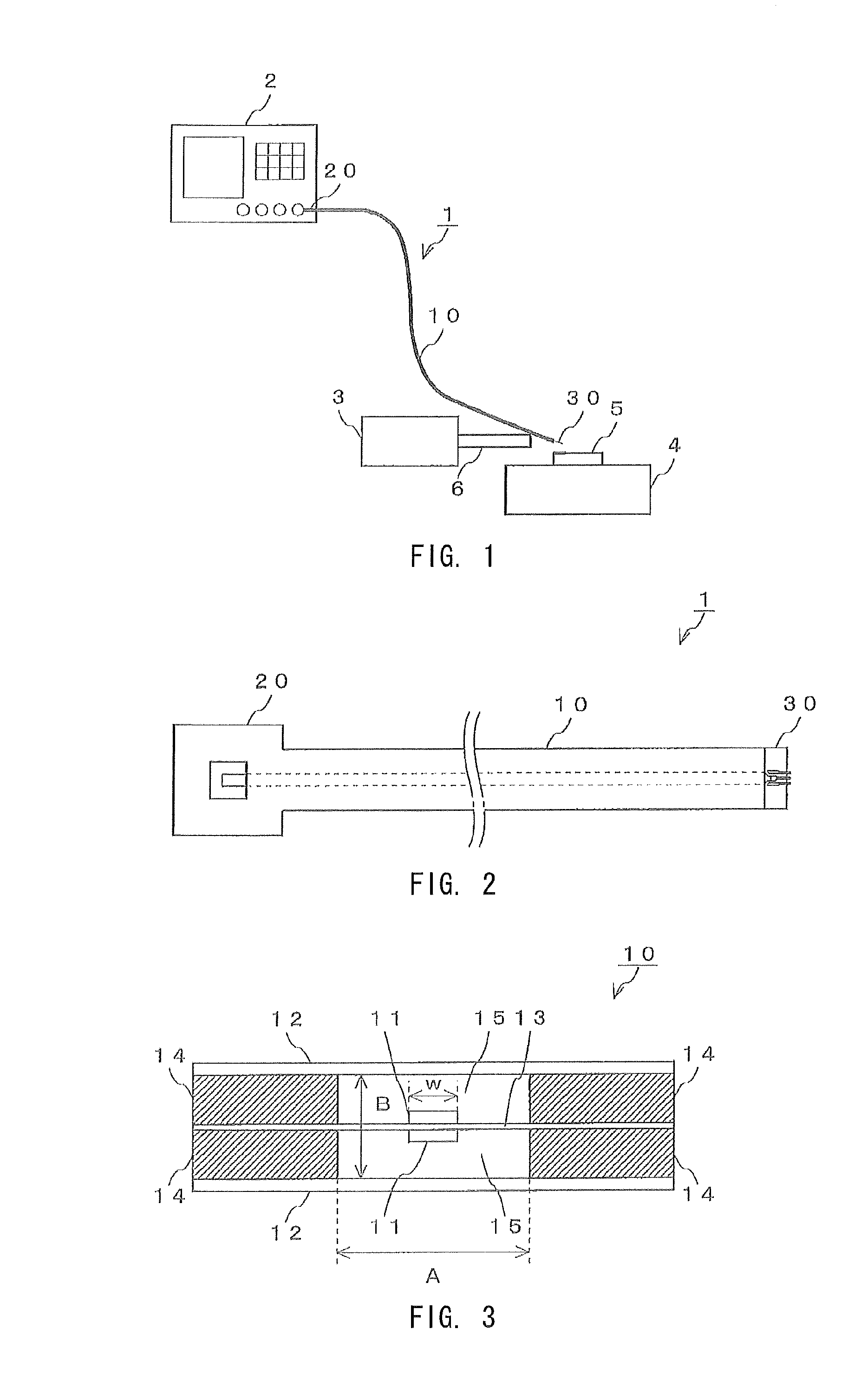
[0083]The description given above employs a mode in which the measuring apparatus 2 measures an output from the device to be measured 5. The present invention is also applicable to a mode in which power is fed from the probe portion 30 to the device to be measured 5. In other words, the present invention may employ a structure in which an input signal from a signal generator or the like is input to the device to be measured 5 by the unitary probe 1, in addition to a structure in which an output signal from the device to be measured 5 is transmitted to the measuring apparatus 2 by the unitary probe 1.

[0084]The probe portion 30 of the unitary probe 1 may be replaced with the waveguide conversion portion 20 so that the waveguide conversion portion 20 maybe formed in both ends of the transmission line portion 10.

[0085]In this structure, two waveguides can be connected to each other by the transmission line portion 10. This makes it possible to transmit high frequency signals between two...


PUM


Abstract

A signal transmission medium for transmitting EHF band signals from a first point to a second point, including: a first end at which a signal exchange with the first point takes place; a second end at which a signal exchange with the second point takes place; and a transmission line portion which is flexible and connects the first end and the second end. The transmission line portion includes: strip conductors which are formed substantially down a center of a flexible printed circuit board to establish electrical connection between a signal line at the first end and a signal line at the second end; and a pair of grounding sheets which are arranged in parallel to each other at a substantially constant gap from the flexible printed circuit board in 180-degree opposite directions. The cavities are formed between the pair of grounding sheets and the strip conductors.

Description

TECHNICAL FIELD[0001]The present invention relates to a signal transmission medium for transmitting mainly high frequency signals, such as signals in the extremely high frequency (EHF) band (30 [GHz] to 3,000 [GHz]), between two devices.BACKGROUND ART[0002]The transmission / reception of signals between devices is stable in wired signal transmission. The signal transmission rate is increasing year after year, and transmitting high frequency signals in the EHF band over a wire is being put into practice. The signal transmission medium used for transmitting signals between devices therefore needs to be capable of handling signals with increased transmission rates as well. In addition to simple signal transmission between two devices, signal transmission media are used in, for example, an evaluation of the characteristics of a semiconductor chip that processes EHF band high frequency signals, for the purpose of connecting the semiconductor chip to be evaluated and a measuring apparatus.[...

Claims


Application Information

Patent Timeline
Patent Type & Authority Applications(United States)
IPC IPC(8): H01P5/02H01P3/08
CPCH01P3/08G01R1/24H01P5/028H01P3/087H01P5/107G01R1/067
Inventor ISHII, YASUNOBUHORIE, RYOTAKASE, SHINTAROYANAGISAWA, WASUKE
Owner YOKOWO CO LTD
Why Eureka
Try Eureka