Real Time Threat Detection System

Active Publication Date: 2014-01-30
THERMAL MATRIX USA
View PDF5 Cites 43 Cited by
  • Summary
  • Abstract
  • Description
  • Claims
  • Application Information

AI Technical Summary

Benefits of technology

[0037]The system provides enhanced detection capabilities of concealed objects by incorporating multiple sensors imaging multiple complimentary and disparate spectra, including thermal imaging devices, millimeter wave sensors and terahertz sensors in a comprehensive, holistic architecture capable of detecting a wide array of concealed articles, such as improvised explosive devices. The architecture provides maximized Probability of Detection (Pd), minimized Probability of False Alarm (Pfa), and increased breath of detectable concealed objects due to the disparate spectra and capabilities of the sensors utilized in the system. Computer assisted or automated algorithms holistically evaluate detection results for increased Pd, decreased Pfa, and reduce operator work load through sensor fusion, providing a cohesive,

Problems solved by technology

This is especially significant since some threats like plastic explosives, powders, liquids and gels cannot be detected using other forms of security devices such as metal detectors.
One disadvantage of these passive security systems, and security systems in general, is they typically image using a select subset of the electromagnetic spectrum as defined by their respective sensor/receiver.
Many such passive systems employ a single sensor imaging in the infrared, millimeter wave, terahertz or x-ray band, resulting in a reduction the effectiveness of the detection.
Passive infrared systems may offer significant standoff distances but image thermal conduction through the clothes instead of penetrating the clothing.
Passive millimeter wave systems excel at detecting metal objects but perform worse detecting liquids.
Passive terahertz sensors image through clothing more readily than millimeter wave but suffer greater effects of solar loading outdoors.
A second disadvantage of typical passive security systems is the lack of computer-assisted or automated detection capability.
Prior art concealed object imaging and detection systems typically lack computer-assisted or automated detection, or confine such computer-assisted or automated detection to a single frequen

Method used


Image

  • Real Time Threat Detection System
  • Real Time Threat Detection System
  • Real Time Threat Detection System

Examples


Example

[0053]In the following detailed description of the preferred embodiments, reference is made to the accompanying drawings, which form a part thereof, and within which are shown by way of illustration specific embodiments by which the system may be practiced. It is to be understood that other embodiments may be utilized and structural changes may be made without departing from the scope of the system.

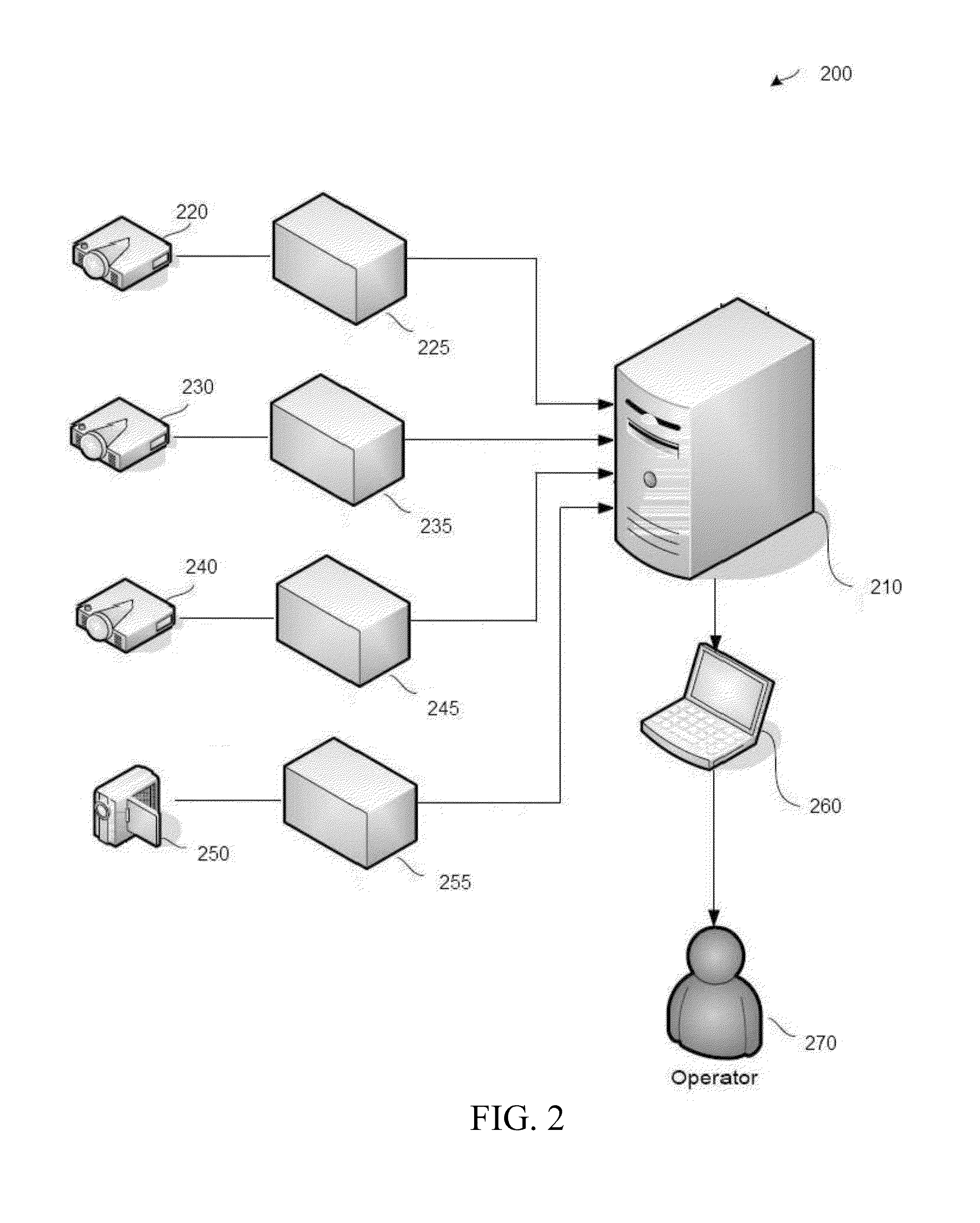
[0054]In a particular embodiment, a system and method for passive multi-spectral imaging is disclosed. The method and system includes provision for imaging, analyzing and displaying imagery from a plurality of passive sensors imaging disparate spectrum conducive to detection of concealed objects.

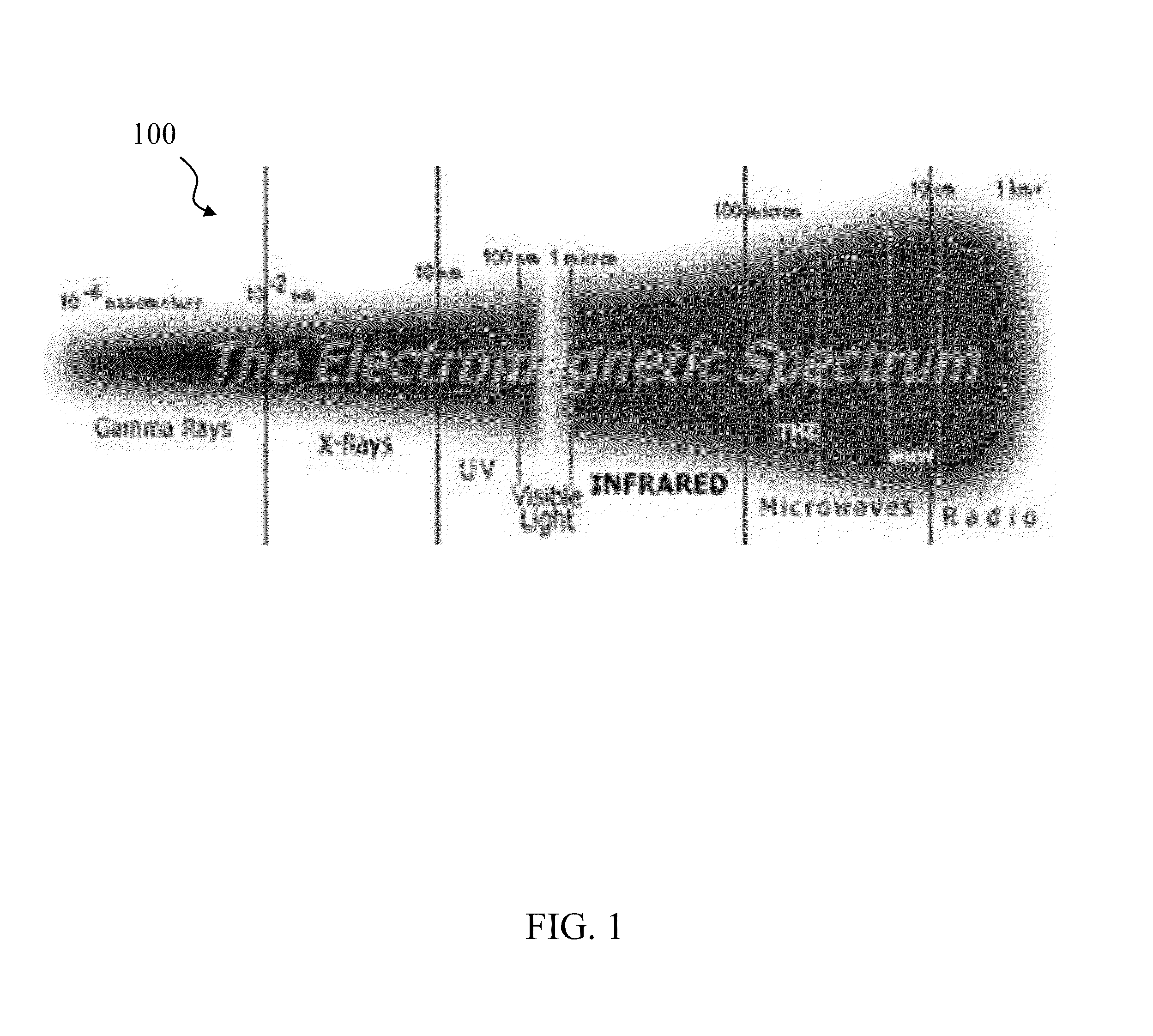
[0055]In one embodiment, the threat detection system is adapted to detect threats posed by pedestrian suicide bombers and the like. In one embodiment, the threat detection system includes a suite of passive sensors adapted to detect radiation spanning the majority of the electromagnetic spectrum.

[...


PUM


Abstract

A real-time threat detection system incorporating a plurality of sensors adapted to detect radiation across the majority of the electromagnetic spectrum. The system also includes an aided or automatic target recognition module which compares the data from the sensors against known radiation signatures and issues an alert when an anomalous signature is detected. The system further includes an operator station which displays sensor information allowing the operator to intervene. The sensors detect radiation which is normally emitted by persons or other bodies and display areas to the operator where normal emissions are blocked.

Description

CROSS REFERENCE TO RELATED APPLICATIONS[0001]This application is a continuation-in-part of and claims priority to currently pending U.S. patent application Ser. No. 11 / 870,862, entitled “Real Time Threat Detection System”, filed Oct. 11, 2007, which claims priority to U.S. Provisional Patent Application No. 60 / 829,041, entitled “Real-Time Threat Detection System”, filed Oct. 11, 2006, both of which are incorporated by reference into this disclosure.STATEMENT OF GOVERNMENT INTEREST[0002]This application is a Continuation in Part for a real time threat detection system made with Government support under Grant No. W15P7T-06-L-9613 awarded by The Department of Defense. The Government, therefore, has certain rights in the system.COPYRIGHT[0003]This application includes material which is subject to copyright protection.[0004]The copyright owner has no objection to the facsimile reproduction of the disclosure as it appears in the Patent and Trademark Office, but otherwise reserves all copy...

Claims


Application Information

Patent Timeline
IPC IPC(8): G08B13/24G06K9/00
CPCG06K9/00771G08B13/2494G06V20/194G06V20/52G06V2201/05
Inventor REINPOLDT, MICHAEL A.REINPOLDT, III, WILLEM H.
Owner THERMAL MATRIX USA
Why Eureka
Try Eureka