
Emitter for vertically polarized wireless signals

Active Publication Date: 2014-01-30
DELPHI DEUTLAND
View PDF4 Cites 8 Cited by
  • Summary
  • Abstract
  • Description
  • Claims
  • Application Information

AI Technical Summary

Benefits of technology

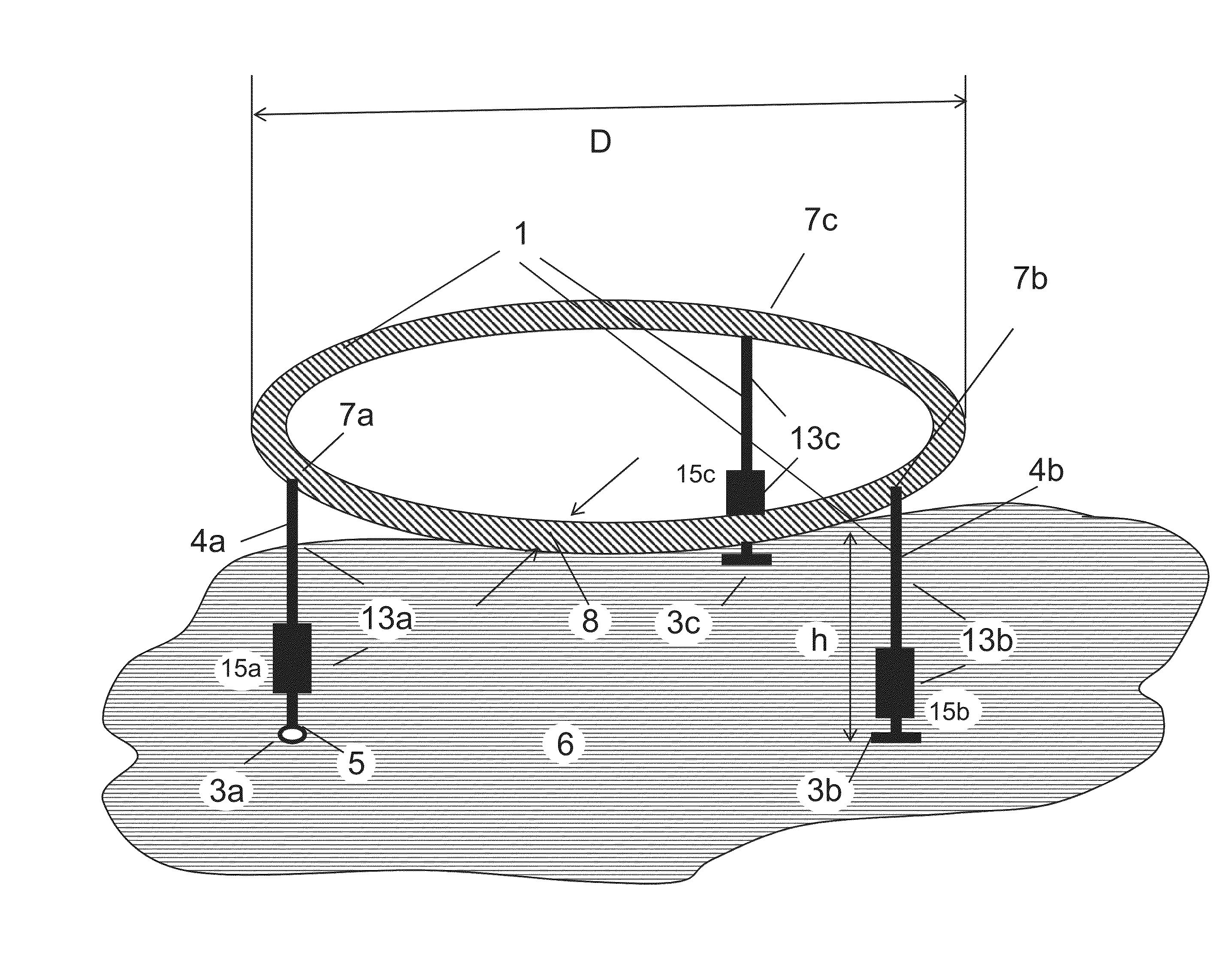
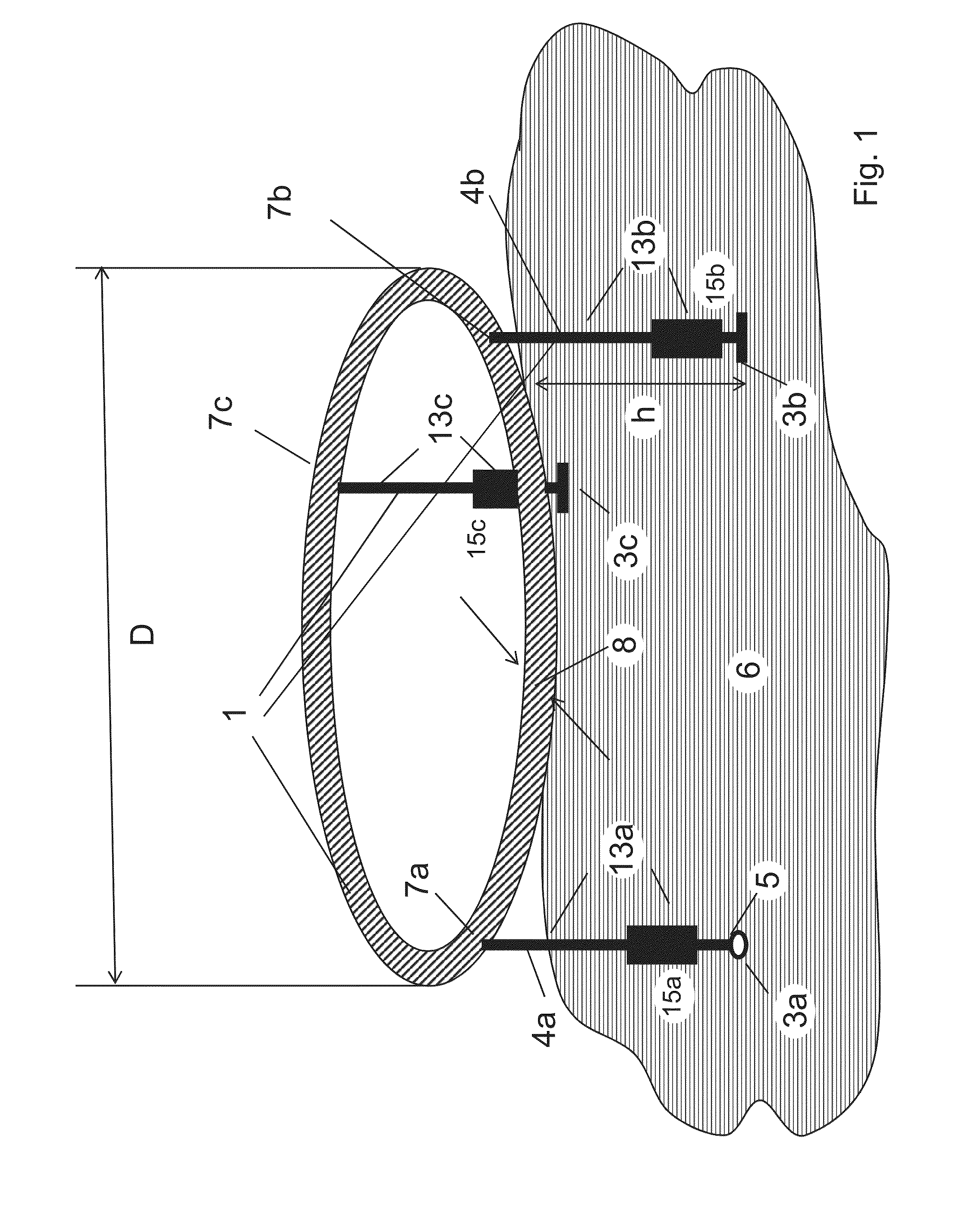
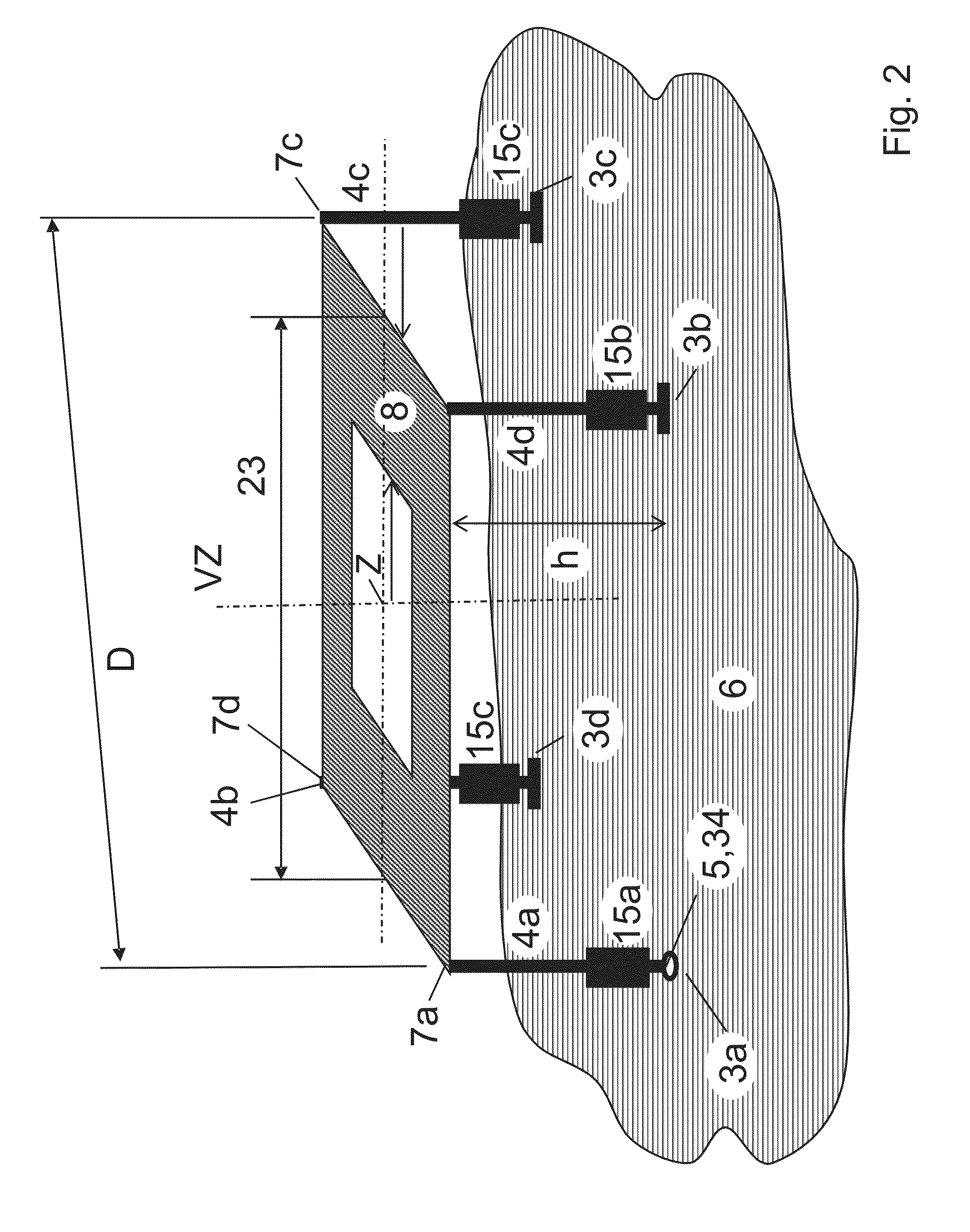
The invention is about a new type of emitter that can be used for wireless communication in vehicles. This emitter has the following technical effects: 1. It has a low electrical height and high mechanical stability, which means it can be easily attached to an aerial. 2. Its impedance is close to the standard for wireless communication systems, so it can be used with different types of aerials without needing a separate matching network. 3. Its vertical directional diagram can be made flat, which increases its gain and makes it more suitable for flat radiation. 4. It can be manufactured as a thin and stable structure, which allows it to be combined with other vertically polarised aerials. 5. It can be designed to be circularly polarised, which widened its frequency range and usefulness for satellite wireless signals. 6. It can have its center region left empty, allowing for the mounting of additional aerials for other wireless services.

Problems solved by technology

Often with good aerial performance it is not possible and not appropriate to cover a number of wireless communication services which operate in frequency ranges which are in each case relatively narrow, but relatively far apart from each other in frequency, with an aerial which works in broadband mode.
Often the wireless signals of the different wireless communication services are also emitted with different polarisation, so that it is not appropriate to meet the different requirements with one aerial.

Method used


Image

  • Emitter for vertically polarized wireless signals
  • Emitter for vertically polarized wireless signals
  • Emitter for vertically polarized wireless signals

Examples


Embodiment Construction

[0030]The description of the manner of operation of an emitter according to the invention can be given by illustration with the aid of a comparison with the electrically small monopole rod emitter in FIG. 4a already mentioned above and referred to as the reference emitter 29, with top load 11 and an inductance Lm, 15 at the base according to the state of the art. Its base impedance at the emitter infeed point 5 is capacitive at low frequencies and, if a suitable inductance Lm 15 is chosen at the frequency fo of a wireless communication service considered here, assuming a low-resistance resonance having the character of a series resonance circuit with the very low resonance resistance Rsm / ZL=0.06 with respect to ZL=50 ohms This known impedance curve is shown as an example in the frequency range around the resonance fo=1.5 GHz for the emitter shown with the dimensions given and the resonance resistance Rsm / ZL=0.06 which is extremely unfavourable for impedance conversion to the resista...


PUM


Abstract

An electric emitter for vertically polarised wireless signals for a communication service with a narrow frequency bandwidth around a frequency fo with free-space wavelength λo in the gigahertz range, comprising at least one substantially horizontally oriented conductor loop arranged above a conductive base area, with an emitter infeed point for electromagnetic excitation of the loop relative to the base area. The loop is formed by a circularly closed ring conductor running in a substantially horizontal plane with a height h of less than λo / 6 over the base area. Distributed over the periphery of the ring conductor are at least three vertical emitters electromagnetically coupled to the ring conductor coupling points and running to the base area, wherein at least two of the emitters are electromagnetically coupled to the base area at earth terminal points, and a vertical emitter is excited via the emitter infeed point at the lower end thereof.

Description

TECHNICAL FIELD OF THE INVENTION[0001]The invention relates to an electric emitter for vertically polarised wireless signals for a wireless communication service with a narrow frequency bandwidth around a frequency fo with free-space wavelength λo in the gigahertz range for preferential use on vehicles.BACKGROUND OF THE INVENTION[0002]Due to the large number of wireless communication services of which the availability has become indispensable in vehicles, in the design of aerials a small overall installed size in conjunction with as low a height as possible is particularly important. Often with good aerial performance it is not possible and not appropriate to cover a number of wireless communication services which operate in frequency ranges which are in each case relatively narrow, but relatively far apart from each other in frequency, with an aerial which works in broadband mode. Often the wireless signals of the different wireless communication services are also emitted with diff...

Claims


Application Information

Patent Timeline
IPC IPC(8): H01Q7/00
CPCH01Q7/00
Inventor LINDENMEIER, STEFANLINDENMEIER, HEINZHOPF, JOCHENREITER, LEOPOLD
Owner DELPHI DEUTLAND
Learn More