Strength proof test method and device to be used therein

a technology of strength proof test and test method, which is applied in the field of proof test, can solve the problems of in vivo fracture risk of ceramic materials used as such biomaterials, more sensitive defects in ceramic materials, etc., and achieve the effect of improving the reliability of strength proof tes

Inactive Publication Date: 2014-02-06
TOKYO METROPOLITAN UNIVERSITY +1
View PDF2 Cites 7 Cited by
  • Summary
  • Abstract
  • Description
  • Claims
  • Application Information

AI Technical Summary

Benefits of technology

[0017]The strength proof test method of the present invention makes it possible to improve the reliability of a strength proof test because parts causing the occurrence of damage in the strength proof test can be removed by an acoustic emission measurement.

Problems solved by technology

However, ceramic materials are more sensitive to defects as compared with metal or other materials, and their fracture probability is known to conform to the Weibull distribution.
However, ceramic materials used as such biomaterials have a risk of in vivo fracture, and even in clinical practice, for example, the fracture of femoral head or others is sometimes reported, which has become an important problem to be solved.

Method used


Image

  • Strength proof test method and device to be used therein
  • Strength proof test method and device to be used therein
  • Strength proof test method and device to be used therein

Examples


example 1

[0041](1) Consideration of Applied Load in the Strength Proof Test

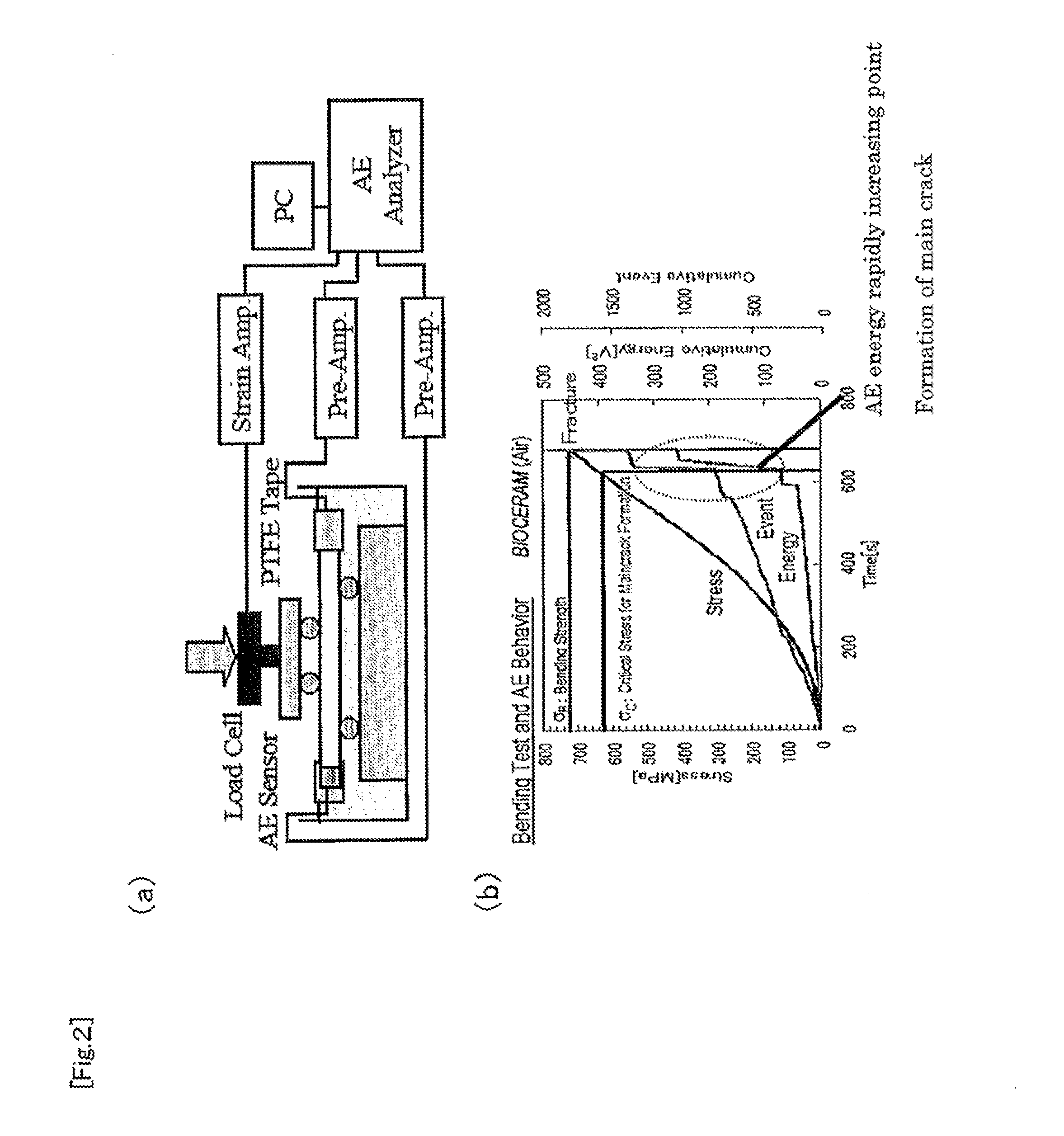
[0042]A bending test was carried out using high-purity alumina (having a purity of 99.9% or higher). Test pieces have a size of 3 mm×4 mm×40 mm, and the surface of each test piece was mirror-finished. As the bending test was adopted a four-point bending test (10 mm in inner span and 30 mm in outer span) in conformity to JIS R1601, as shown in FIG. 2(a), and the test was carried out in water. To both ends of each test piece were attached AE sensors, and the occurrence of defect in the test piece was monitored by the AE method. The AE measurement conditions were as follows: the gain of a preamplifier, 60 dB; the measurement threshold, 1.8 μV in terms of preamplifier input power; and the measurement frequency region, 95 to 660 kHz.

[0043]First, 129 test pieces were subjected to the four-point bending test at a crosshead speed of 0.1 mm / min to measure main crack forming critical stress σc (the stress at the point of rapidl...

example 2

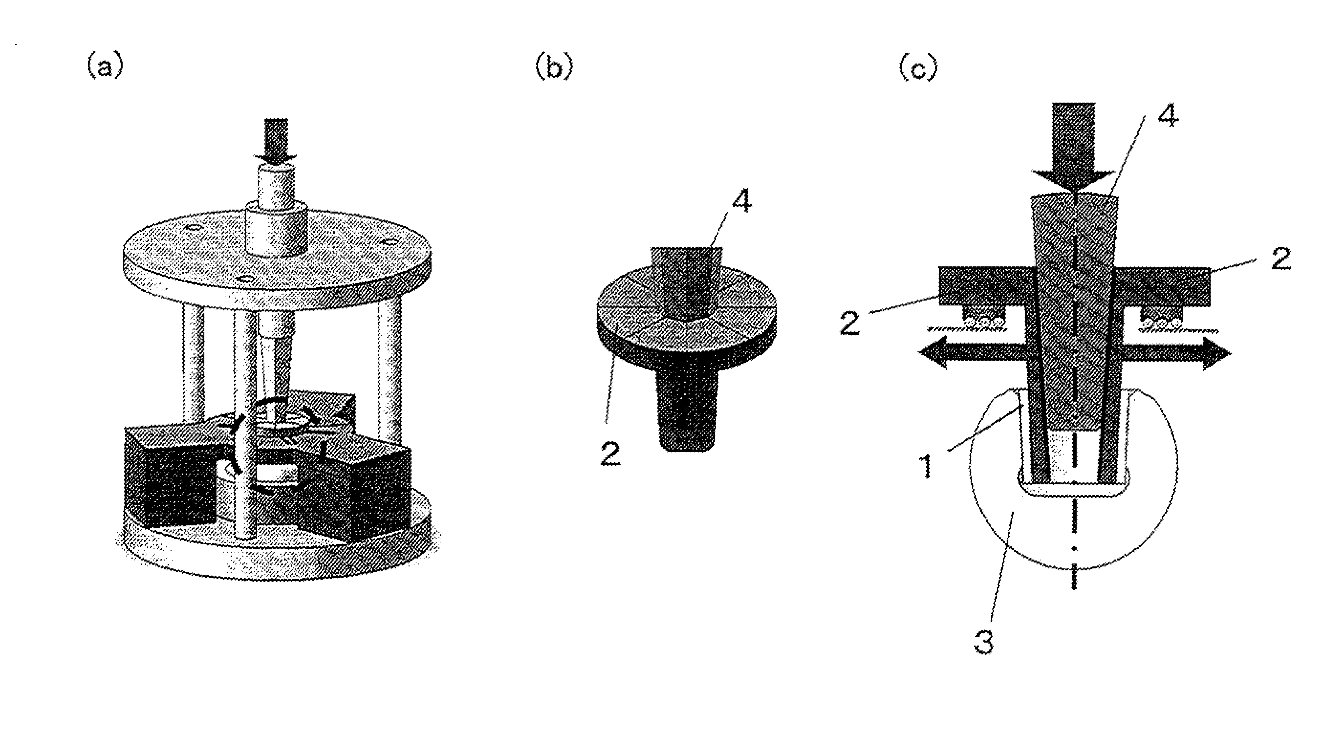
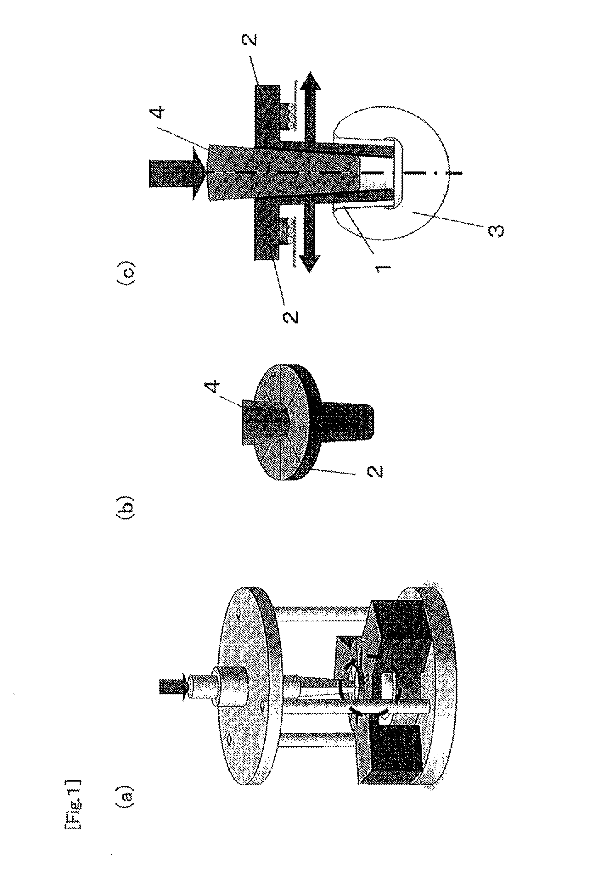
[0050]In this Example, the compression test of femoral heads for artificial hip joint was carried out using a device shown in FIG. 1. The device shown in FIG. 1 comprises acoustic emission sensors (not shown) to be attached in place of the femoral head, a rubber member 1, a tapered split segment 2 capable of being split along the axial direction thereof, and a tapered rod 4 having the same taper angle as that of the tapered split segment 2 and being to be inserted in the inside of the split segment 2. In this Example, the rubber member 1 is made of urethane rubber.

[0051]The tapered split segment 2 is disposed in contact, through the intermediary of the rubber member 1, with the inside of a cavity of the femoral head 3 in such a manner that the tapered portion is directed downwardly in the vertical direction, which femoral head is to be disposed with the cavity being directed upwardly in the vertical direction. As the femoral head was used an alumina femoral head (having a purity of ...


PUM

PropertyMeasurementUnit
sizeaaaaaaaaaa
frequencyaaaaaaaaaa
fracture strengthaaaaaaaaaa

Abstract

The present invention is intended for improving the reliability of a strength proof test method for ceramic parts. The present invention is directed to a strength proof test method for making total inspection of ceramic parts, including: applying a prescribed load to the ceramic parts; and at the same time, making an acoustic emission measurement, in which the ceramic parts are considered as passing when the ceramic parts are not fractured in the test and the variation of acoustic emission energy is not more than a threshold.

Description

TECHNICAL FIELD[0001]The present invention relates to a proof test, and more particularly, it relates to a strength proof test method for ceramic parts particularly sensitive to defects and a device to be used therein.BACKGROUND ART[0002]Ceramic materials are excellent in characteristics such as hardness, in vivo stability, and heat resistance; therefore, the field of their application involves aerospace materials and biomaterials. However, ceramic materials are more sensitive to defects as compared with metal or other materials, and their fracture probability is known to conform to the Weibull distribution.[0003]When ceramic materials are used as, for example, biomaterials, they are widely used as, for example, artificial joint prostesis or dental implant, and since they have excellent sliding characteristics and wear resistance, they are preferably used as artificial femoral heads, acetabular liners, knee joint femoral component, and others, in particular. However, ceramic materia...

Claims


Application Information

Patent Timeline
Patent Type & Authority Applications(United States)
IPC IPC(8): G01N29/14
CPCG01N29/14A61C19/04A61F2/3609A61F2/468G01N3/08G01N2203/0087G01N2203/0248G01N2203/0658G01N2291/0232
Inventor WAKAYAMA, SHUICHIIKEDA, JUNJI
Owner TOKYO METROPOLITAN UNIVERSITY
Why Eureka
Try Eureka