Automated assembly sensor cable

a sensor cable and automatic technology, applied in the direction of power cables, cables, insulated conductors, etc., can solve the problem that the arrangement of cables does not readily lend itself to an automated assembly process, and achieve the effect of adding strength to the body

Active Publication Date: 2014-02-06
JPMORGAN CHASE BANK NA
View PDF13 Cites 284 Cited by
  • Summary
  • Abstract
  • Description
  • Claims
  • Application Information

AI Technical Summary

Benefits of technology

[0012]A further aspect of an automated assembly sensor cable is a generally wide and flat elongated body. A conductor set means is disposed within the body for transmitting drive currents to sensor LEDs and for receiving currents from sensor photodiodes. A registration means indentifies the relative locations of the conductor set means so as to automate attachment of connectors and c

Problems solved by technology

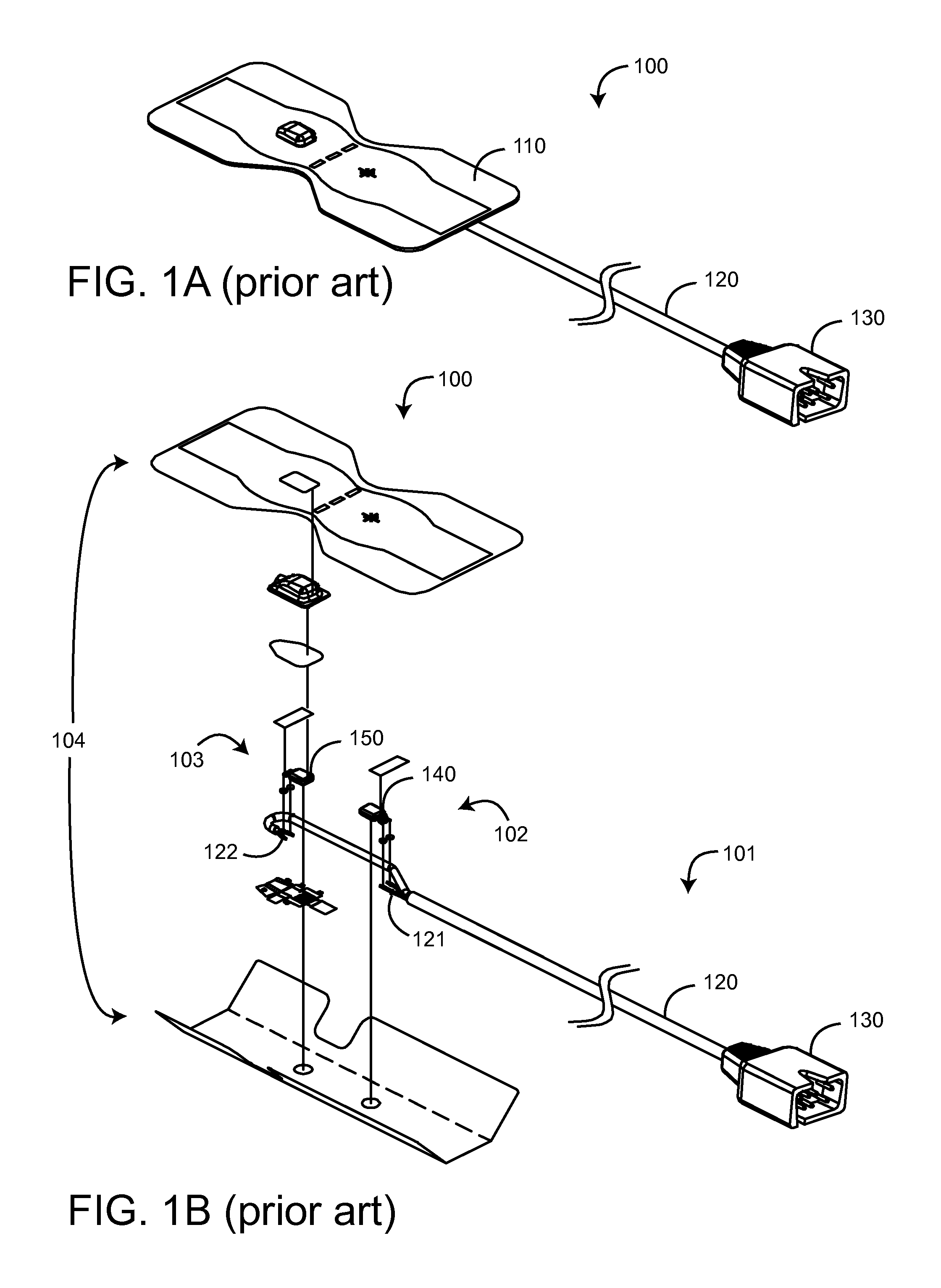
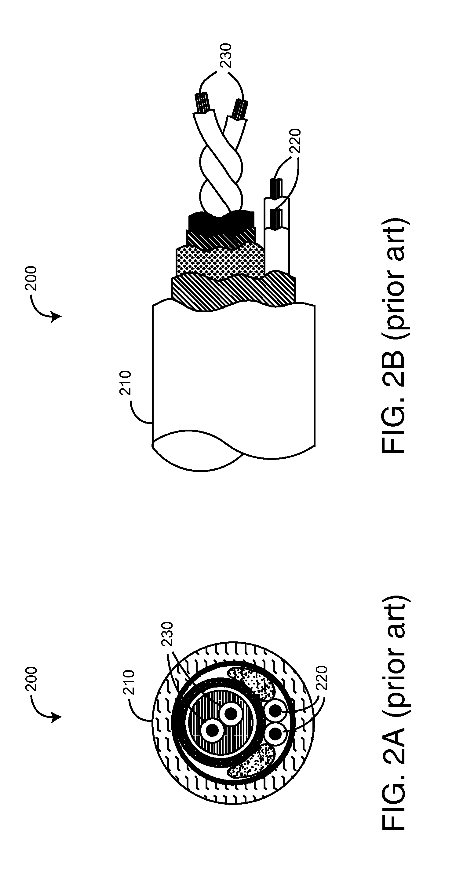
Disadvantageously, this cable arrangement does not r

Method used


Image

  • Automated assembly sensor cable
  • Automated assembly sensor cable
  • Automated assembly sensor cable

Examples


Embodiment Construction

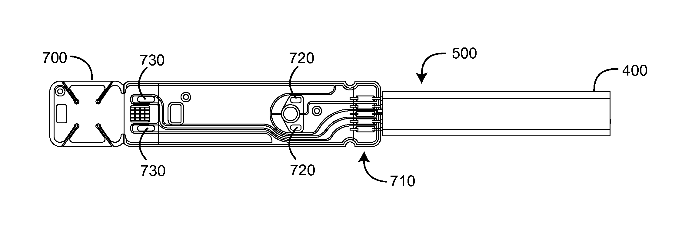
[0019]FIGS. 3A-G illustrate an automated assembly sensor cable 300 embodiment having a relatively flat and wide body 301 with linearly-arranged conductors sets 310, 320 and a machine-readable registration feature 360 so as to facilitate automatic location and attachment of specific conductors to specific connector pins or pads, as described with respect to FIGS. 4-6, below. In a particular embodiment, the sensor cable has a PVC semi-pressure extruded outer jacket 350 and a co-extruded conductive PVC inner jacket 340. The inner jacket 340 surrounds the conductor sets 310, 320 and an embedded drain line 330. The inner jacket 340 acts as a conductor shield, replacing conventional braided wire shielding. In an embodiment, Kevlar fibers are added to the outer jacket 350 for strength. In an embodiment, the registration feature 360 is a centralized groove formed in the surface of the outer layer during extrusion. In another embodiment, the registration feature is a printed line on the oute...


PUM


Abstract

An automated assembly sensor cable has a generally wide and flat elongated body and a registration feature generally traversing the length of the body so as to identify the relative locations of conductors within the body. This cable configuration facilitates the automated attachment of the cable to an optical sensor circuit and corresponding connector. In various embodiments, the automated assembly sensor cable has a conductor set of insulated wires, a conductive inner jacket generally surrounding the conductor set, an outer jacket generally surrounding the inner jacket and a registration feature disposed along the surface of the outer jacket and a conductive drain line is embedded within the inner jacket. A strength member may be embedded within the inner jacket.

Description

PRIORITY CLAIM TO RELATED PROVISIONAL APPLICATIONS[0001]The present application claims priority benefit under 35 U.S.C. §119(e) to U.S. Provisional Patent Application Ser. No. 61 / 678,107, filed Aug. 1, 2012, titled Automated Assembly Sensor Cable, hereby incorporated in its entirety by reference herein.BACKGROUND OF THE INVENTION[0002]Pulse oximetry is a widely accepted noninvasive procedure for measuring the oxygen saturation level of arterial blood, an indicator of a person's oxygen supply. A typical pulse oximetry system utilizes an optical sensor clipped onto a fingertip to measure the relative volume of oxygenated hemoglobin in pulsatile arterial blood flowing within the fingertip. Oxygen saturation (SpO2), pulse rate and a plethysmograph waveform, which is a visualization of pulsatile blood flow over time, are displayed on a monitor accordingly.[0003]Conventional pulse oximetry assumes that arterial blood is the only pulsatile blood flow in the measurement site. During patient...

Claims


Application Information

Patent Timeline
IPC IPC(8): H01B9/02
CPCH01B9/028A61B5/14552H01B7/0823H01B7/0861H01B7/36Y10T29/49149Y10T29/49174Y10T29/49147
Inventor AL-ALI, AMMARABDUL-HAFIZ, YASSIRMACNEISH, III, WILLIAM JACKFORREST, KEVIN
Owner JPMORGAN CHASE BANK NA
Why Eureka
Try Eureka