
Charged Particle Optics with Azimuthally-Varying Third-Order Aberrations for Generation of Shaped Beams

a technology of charged particles and aberrations, applied in the field of charged particle optics, can solve the problems of greater complexity and cost, and achieve the effect of simplifying the optical system

Inactive Publication Date: 2014-02-06
PARKER N WILLIAM
View PDF4 Cites 11 Cited by
  • Summary
  • Abstract
  • Description
  • Claims
  • Application Information

AI Technical Summary

Benefits of technology

The invention is a device that allows for complete control over the shape of a beam of light generated using a special optical element. By adjusting a parameter called N, the device can create square or rectangular beams with precise control over their shape and edge acuity. The first embodiment is simpler and cheaper, but the second embodiment provides more complete control over the beam profile.

Problems solved by technology

However, large values of N result in greater complexity and cost.

Method used


Image

  • Charged Particle Optics with Azimuthally-Varying Third-Order Aberrations for Generation of Shaped Beams
  • Charged Particle Optics with Azimuthally-Varying Third-Order Aberrations for Generation of Shaped Beams
  • Charged Particle Optics with Azimuthally-Varying Third-Order Aberrations for Generation of Shaped Beams

Examples


first embodiment

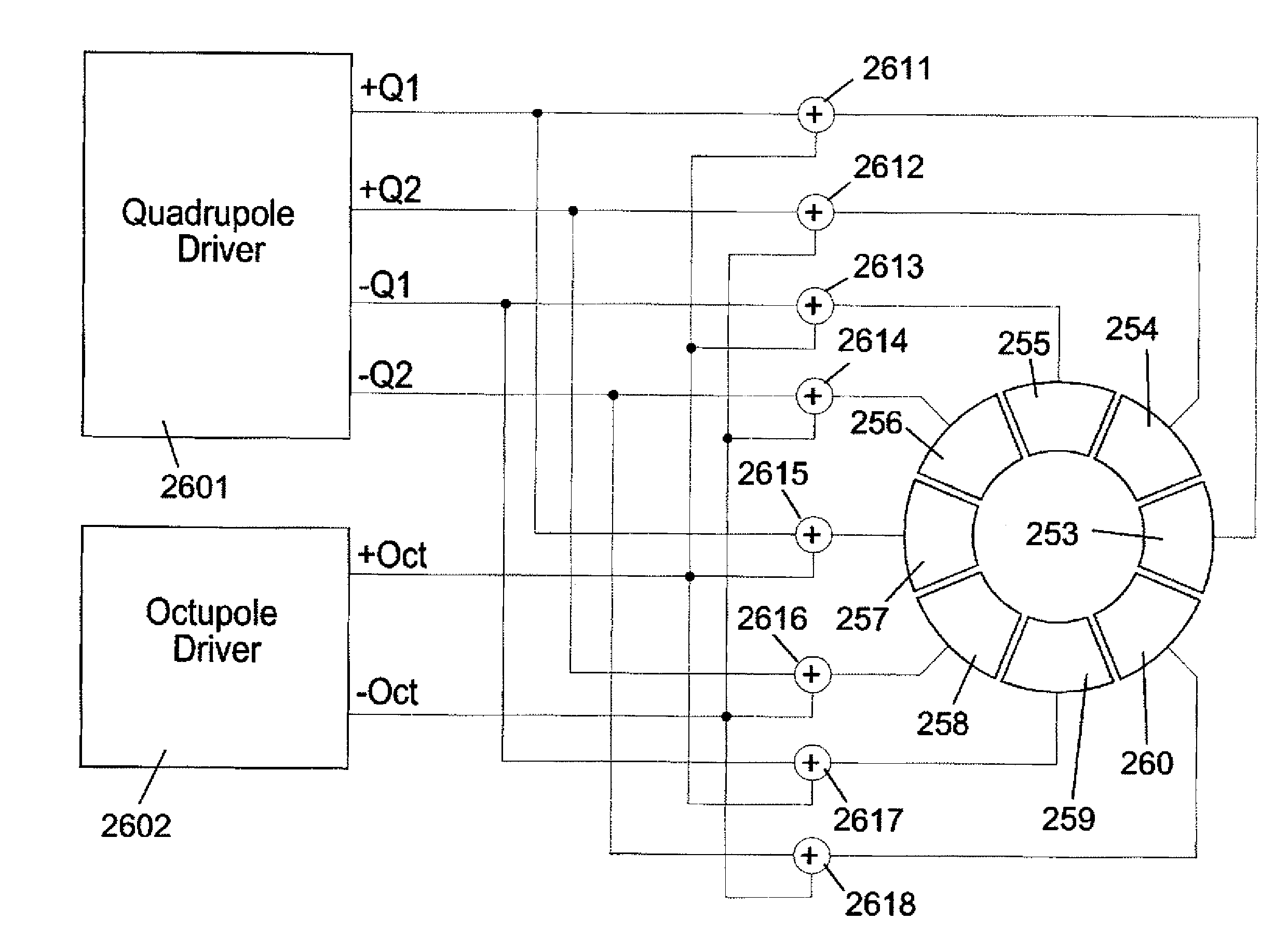
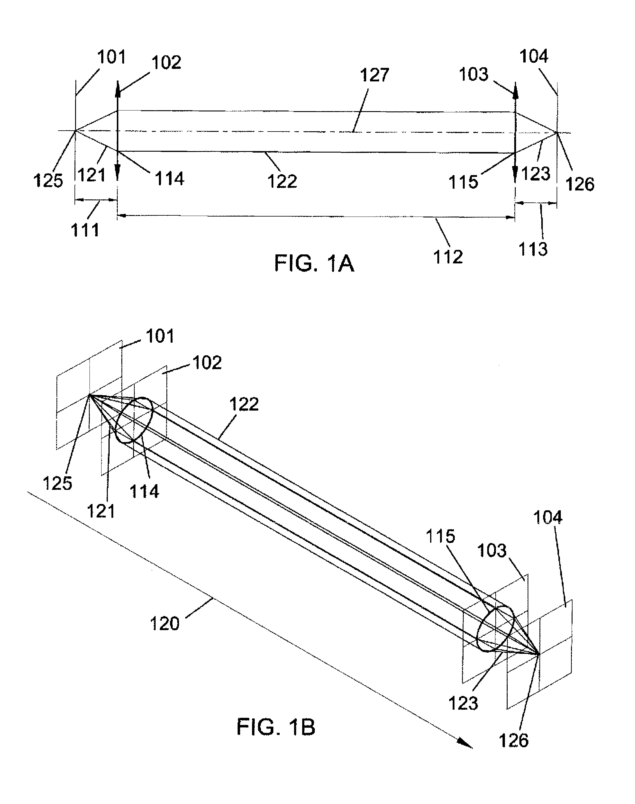
[0072]FIG. 6 shows a schematic side view of a first embodiment of the present invention. Electrons 218 are emitted from electron source 215 in object plane 201, which can be a thermionic source, a LaB6 emitter, a cold field emitter, a Schottky emitter, or other type of electron source as is familiar to those skilled in the art. The particular type of electron source is not part of the present invention. Gun lens 202 (with focal length 211) focuses electrons 218 into an approximately parallel electron beam 219 which passes down the column a distance 212 before reaching octupole 203. Octupole 203 may be implemented in the column using an element with 8N poles, where N=1 (an octupole), 2 (a 16-pole), . . . as is familiar to those skilled in the art. FIG. 7 shows a view of a 16-pole element (N=2). The excitation of octupole 203 is discussed in FIG. 7. Trajectories leaving octupole 203 pass a distance 213 down the column, reaching objective lens 204 (with focal length 214) which focuses ...

second embodiment

[0081]FIGS. 12A-21 illustrate a second embodiment of the present invention. Table IV shows a comparison of the relative advantages and disadvantages of the first and second embodiments of the present invention. The second embodiment utilizes four elements 1203-1206, as shown in FIGS. 12A-B between the gun lens 1202 and the objective lens 1207. Elements 1203-1206 may be implemented using either 16-poles as in FIG. 7, or 8-poles as in FIG. 8.

[0082]FIG. 12A shows a schematic side view of a second embodiment of the present invention in a plane containing two lines: a) a line midway between the +X-axis and +Y-axis, and b) the Z-axis=the optical axis—hereinafter this plane will be referred to as the (+X+Y)−Z plane. FIG. 12B shows a schematic side view of a second embodiment of the present invention in a plane containing two lines: a) a line between the −X-axis and +Y-axis, and b) the Z-axis=the optical axis—hereinafter this plane will be referred to as the (−X+Y)−Z plane. Note that this p...


PUM


Abstract

A charged particle shaped beam column includes: an objective lens configured to form a charged particle shaped beam on the surface of a substrate, wherein the disk of least confusion of the objective lens does not coincide with the surface of the substrate; an optical element with 8N poles disposed radially symmetrically about the optic axis of the column, the optical element being positioned between a condenser lens and the objective lens, wherein integer N1; and a power supply applying excitations to the optical element's 8N poles to provide an octupole electromagnetic field. The octupole electromagnetic field induces azimuthally-varying third-order deflections to beam trajectories passing through the 8N-pole optical element. By controlling the excitation of the 8N poles a shaped beam, such as a square beam, can be formed at the surface of the substrate.

Description

CROSS-REFERENCE TO RELATED APPLICATIONS[0001]This application claims the benefit of U.S. Provisional Applications Ser. Nos. 60 / 895,126 filed Mar. 15, 2007 and 60 / 921,733 filed Apr. 3, 2007.BACKGROUND OF THE INVENTION[0002]1. Field of Use for the Invention[0003]This invention relates to the field of charged particle optics, and in particular to systems for generation of high current density shaped electron beams.[0004]2. Description of the Related Art[0005]The use of electron beams to lithographically pattern semiconductor masks, reticles and wafers is an established technique. The different lithography strategies may be characterized by the following key parameters: beam positioning strategy; and beam shape control.[0006]There are two main approaches to the positioning of electron beams for the exposure of resist during the lithographic process:[0007](a) Raster Scanning, where the beam is moved on a regular two-dimensional lattice pattern. This method has the advantage that the scan...

Claims


Application Information

Patent Timeline
Patent Type & Authority Applications(United States)
IPC IPC(8): H01J3/22H01J37/317H01J3/18
CPCH01J3/22H01J37/317H01J3/18H01J37/3007H01J2237/1534H01J2237/31776
Inventor PARKER, N. WILLIAM
Owner PARKER N WILLIAM
Learn More