Vehicular air cleaner

a technology of vacuum cleaner and vacuum chamber, which is applied in the direction of process control, instruments, separation processes, etc., can solve the problems of troublesome work and easy deterioration of the purifying function of the vacuum chamber, and the need for replacing the vacuum chamber itself independently, so as to increase the ozone purification rate of the vacuum chamber, and increase the temperature of the air passing through the vacuum chamber

Inactive Publication Date: 2014-02-06
TOYOTA JIDOSHA KK
View PDF9 Cites 0 Cited by
  • Summary
  • Abstract
  • Description
  • Claims
  • Application Information

AI Technical Summary

Benefits of technology

[0018]According to the first aspect of the present invention, the purifying function recovery control for increasing the temperature of the ozone purifying element in accordance with the degree of deterioration of the ozone purifying element can be executed. When the temperature of the ozone purifying element is increased, the temperature of air passing through the ozone purifying element becomes high. Accordingly, a probability that the air contacts with the ozone purifying element is increased, and therefore an ozone purification rate of the ozone purifying element is increased. Also, the ozone purification rate of the ozone purifying element is increased as the deterioration of the ozone purifying element continues. Thus, a purifying function of the ozone purifying element can be utilized as much as possible in accordance with the degree of the deterioration of the ozone purifying element according to the present invention.
[0019]As described above, the ozone purification rate of the ozone purifying element is increased as the temperature of the ozone purifying element is increased. However, the life of the ozone purifying element may be shortened by executing the purifying function recovery control because the increased temperature of the ozone purifying element may accelerate the progression of its deterioration. In this regard, the second aspect of the present invention inhibits the execution of the purifying function recovery control until the degree of the deterioration of the ozone purifying element exceeds the reference value. Thus, a needless acceleration of the progression of the deterioration of the ozone purifying element can be inhibited. Thus, the life of the ozone purifying element can be extended according to the present invention.
[0020]According to the third aspect of the present invention, the execution of the purifying function recovery control can be inhibited when the ozone concentration is lower than the set concentration. Under the environmental condition that the ozone concentration in air is low, ozone purifying efficiency by execution of the purifying function recovery control is relatively low. Thus, the life of the ozone purifying element can be extended by effectively executing the control according to the present invention.
[0021]When the vehicle component part is the capacitor of the air conditioner, the temperature of the capacitor becomes high when the temperature of the ozone purifying element is increased by execution of the purifying function recovery control. Accordingly, the in-vehicle temperature may not reach the required temperature. According to the fourth aspect of the present invention, the execution of the purifying function recovery control can be stopped when the temperature difference between the required temperature for the air conditioner and the in-vehicle temperature after elapse of the set time from start of the purifying function recovery control gets out of the set temperature range. Thus, when the temperature difference is not within the set temperature range, a request for cooling the vehicle can be prioritized and the in-vehicle temperature can quickly reach the required temperature.

Problems solved by technology

However, there is a problem that the activated carbon is used as an ozone purifying element, its purifying function is easily deteriorated.
However, for example, the capacitor of the air conditioner constitutes part of a refrigerant circulation circuit, and thus troublesome work is needed to replace the capacitor itself independently.

Method used


Image

  • Vehicular air cleaner
  • Vehicular air cleaner
  • Vehicular air cleaner

Examples


first embodiment

[Structure of Vehicular Air Cleaner]

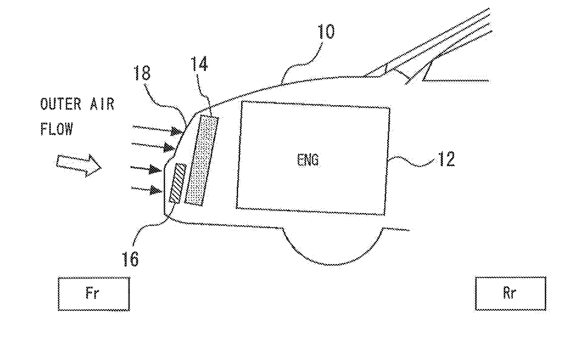
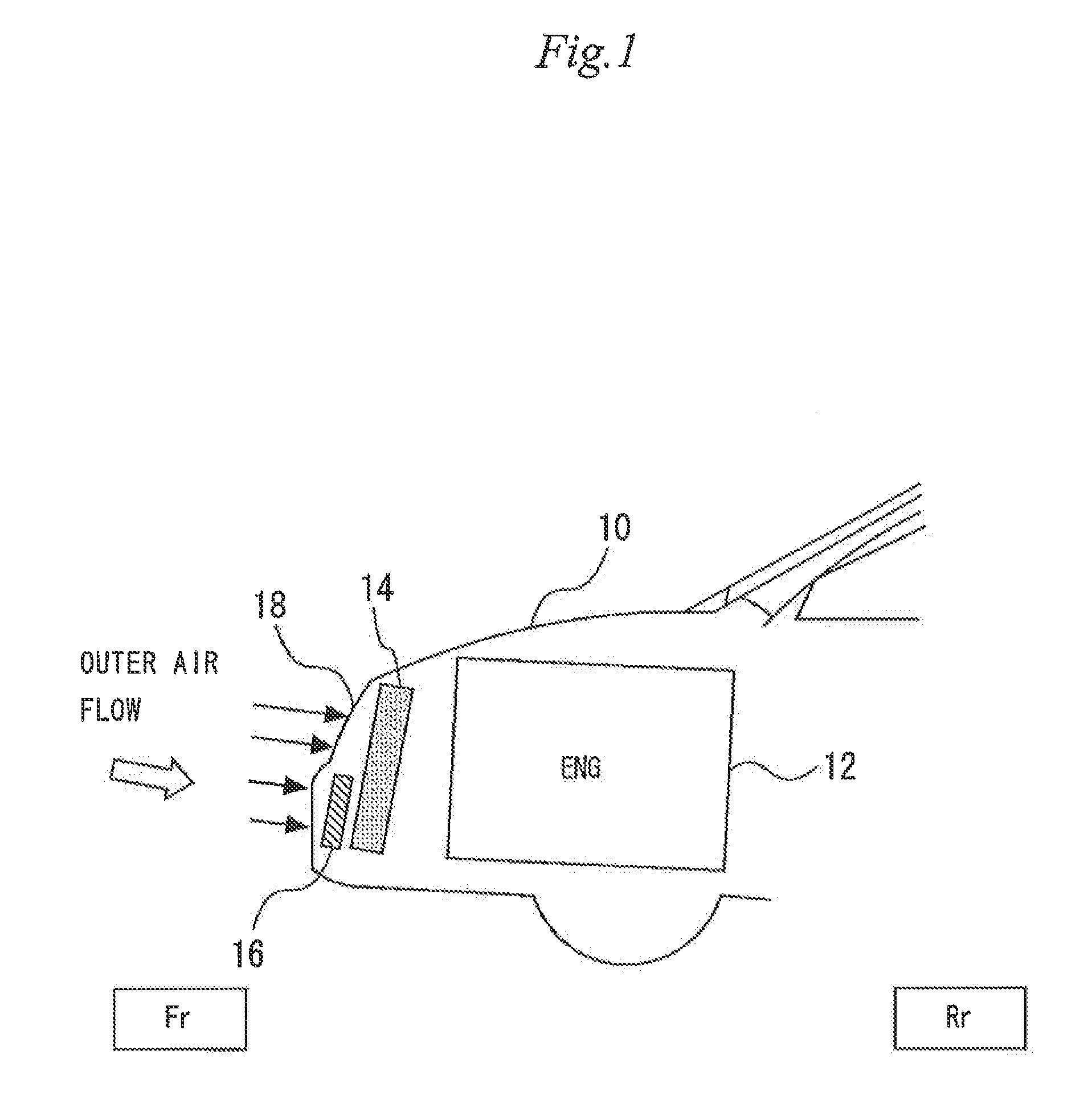
[0031]A first embodiment of the present invention will be explained below with reference to FIGS. 1 to 7. FIG. 1 is a schematic view showing a structure of a vehicle on which an air cleaner is mounted according to the first embodiment. The vehicle 10 includes an internal combustion 12 serving as a power unit. The exhaust gas discharged from the internal combustion 12 contains HC and NOx. Ozone is produced by a photochemical reaction between I-IC and NOx as reactants. Therefore, when the air cleaner is mounted on the vehicle 10 including the internal combustion 12, the ozone is purified while the vehicle 10 is moving. And thus, the damage to the environment caused due to the vehicle 10 can be reduced.

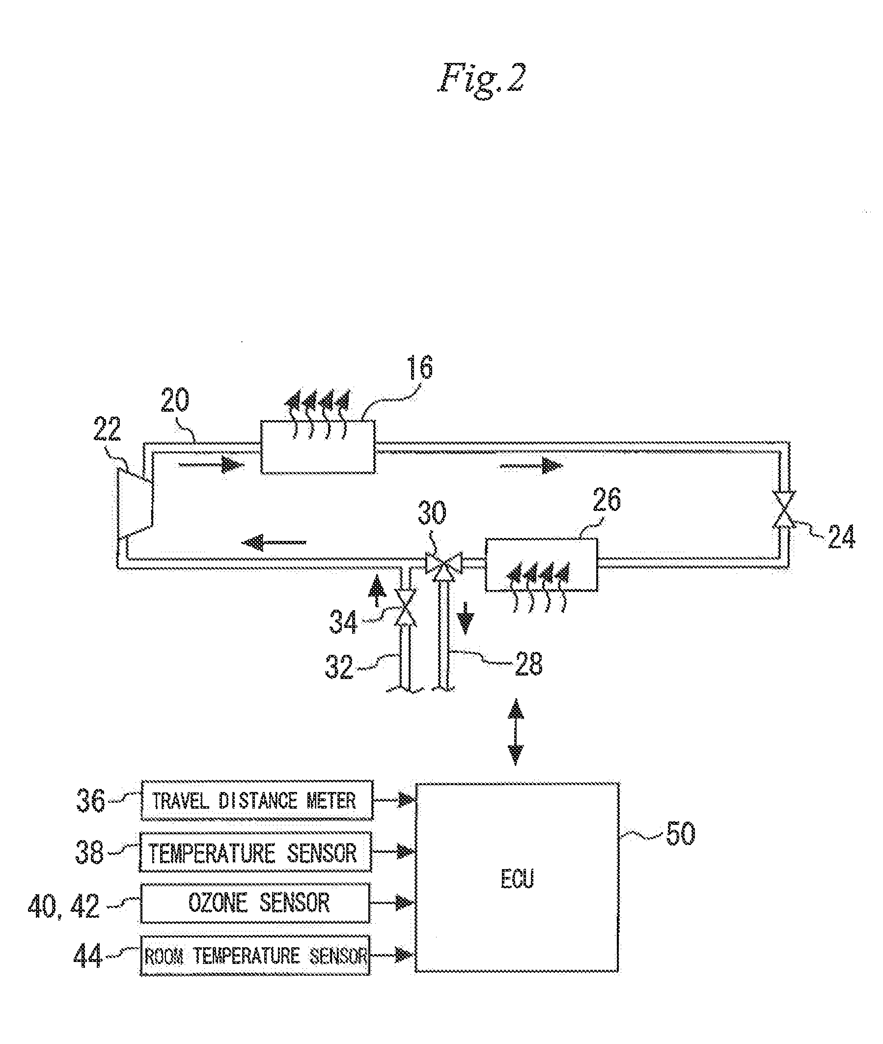
[0032]In the vehicle 10, a radiator 14 for cooling coolant water circulating through the internal combustion 12 is arranged on the front side of the internal combustion 12. A capacitor 16 of an air conditioner is arranged on the front side of the radia...

second embodiment

[0060]Next, the second embodiment of the present invention will be explained below with reference to FIG. 8. In the second embodiment, the purifying function recovery control shown in FIG. 8 is executed with the structure shown in FIGS. 1 and 2. Thus, differences from the first embodiment will be mainly explained below, and a detailed explanation of similar features will be simplified or omitted.

[Characteristics of Second Embodiment]

[0061]In the first embodiment, the ozone purification rate of the activated carbon is increased by increasing the pressure of the compressor 22, which has been described as the purifying function recovery control, when the deterioration rate R of the activated carbon is higher than the predetermined value Rth. However, the execution of the fuel consumption may be deteriorated, which is described above, because the fuel is consumed in accordance with the increased pressure of the compressor 22 for executing the purifying function recovery control. Therefo...

third embodiment

[0069]Next, the third embodiment of the present invention will be explained below with reference to FIG. 9. In the third embodiment, a function recovery stop control shown in FIG. 9 is executed with the structure shown in FIGS. 1 and 2. Thus, differences from the first embodiment will be mainly explained below, and a detailed explanation of similar features will be simplified or omitted.

[Characteristics of Third Embodiment]

[0070]The purifying function recovery control adds the ozone purifying function demand pressure PO3 to the cooling demand pressure PA / C as described above. Thus, an actual in-vehicle temperature Tin may not reach the required temperature Trq. Thus, in the third embodiment, when the temperature difference between the in-vehicle temperature Tin and the required temperature Trq is still generated after the elapse of a predetermined time from the start of the execution of the purifying function recovery control, the execution of the purifying function recovery control...


PUM

PropertyMeasurementUnit
temperatureaaaaaaaaaa
velocitiesaaaaaaaaaa

Abstract

The present invention relates to a vehicular air cleaner. It is an object to provide a DOR system which can utilize a purifying function of an ozone purifying element containing an activated carbon for a long period of time.
As shown in A1 and A2 of FIG. 5, in the activated carbon at an initial state, an ozone purification rate is almost the same at the same wind velocity even when a temperature condition is different, even though the ozone purification rate is changed when the wind velocity is changed. After the endurance test, the ozone purification rate is increased even at the same wind velocity when the temperature becomes high as shown in B1 and B2 of FIG. 5. Thus, the temperature condition difference affects the ozone purification rate more as the deterioration of the activated carbon continues.

Description

TECHNICAL FIELD[0001]The present invention relates to a vehicular air cleaner, more particularly, to a vehicular air cleaner capable of purifying ozone in air.BACKGROUND ART[0002]Ozone, which causes photochemical smog, is produced by a photochemical reaction of HC and NOx contained in exhaust gas from automobiles and factories. Therefore, reducing the amount of HC and NOx emissions from automobiles is an efficient way to suppress the production of ozone and prevent the occurrence of photochemical smog. Also, purifying ozone in air directly can be one of the ways to prevent the occurrence of photochemical smog. The occurrence of photochemical smog can be prevented more effectively not only by reducing the amount of emissions of reactants such as HC and NOx, but also by purifying a product such as ozone. Thus, an automobile provided with a vehicular air cleaner capable of directly purifying ozone in air has been put into practical use in some places including California in the United ...

Claims


Application Information

Patent Timeline
Patent Type & Authority Applications(United States)
IPC IPC(8): A61L9/00
CPCA61L9/00B01D53/66B01D2253/102B01D2257/106B01D2258/06B01D2259/4566Y02A50/20
Inventor SHINODA, YOSHIHISASUGIMOTO, KAZUHIROKATSUMATA, HIROAKI
Owner TOYOTA JIDOSHA KK
Why Eureka
Try Eureka