Fluid treatment system

a treatment system and flue gas technology, applied in the direction of treatment water nature, separation process, vessel construction, etc., can solve the problems of high capital cost of reactors, difficult access, and manifested problems

Active Publication Date: 2014-02-13
TROJAN TECH
View PDF6 Cites 14 Cited by
  • Summary
  • Abstract
  • Description
  • Claims
  • Application Information

AI Technical Summary

Benefits of technology

[0044]In the ballasting mode, water is pumped from the sea or other body of water in which the shipping vessel is located to a ballast fluid inlet in the present fluid treatment system. Thereafter, it passes through the filter separation a...

Problems solved by technology

Certain problems existed with these earlier designs.
These problems were manifested particularly when applied to large open flow treatment systems which are typical of larger scale municipal waste water or potable water treatment plants.
Thus, these types of reactors had associated with them the following problems:relatively high capital cost of reactor;difficult accessibility to submerged reactor and/or wetted equipment (lamps, sleeve cleaners, etc);difficulties associated with removal of fouling materials from fluid treatment equipment;relatively low fluid disinfection efficiency, and/orfull redundancy of equipment was required for maintenance of wetted components (sleeves, lamps and the like).
Since the design of the system inherently comprised a free-surface flow of fluid, there were constraints on the maximum flow each lamp or lamp array could handle before either one or other hydraulically adjoined arrays would be adversely affected by changes in water elevation.
At higher flows or significant changes in the flow, the unrestrained or free-surface flow of fluid would be allowed to change the treatment volume and cross-sectional shape of the fluid flow, thereby rendering the reactor relatively ineffective.
The problem here was that, with less powerful lamps, a relatively large number of lamps was required ...

Method used


Image

  • Fluid treatment system
  • Fluid treatment system
  • Fluid treatment system

Examples


first embodiment

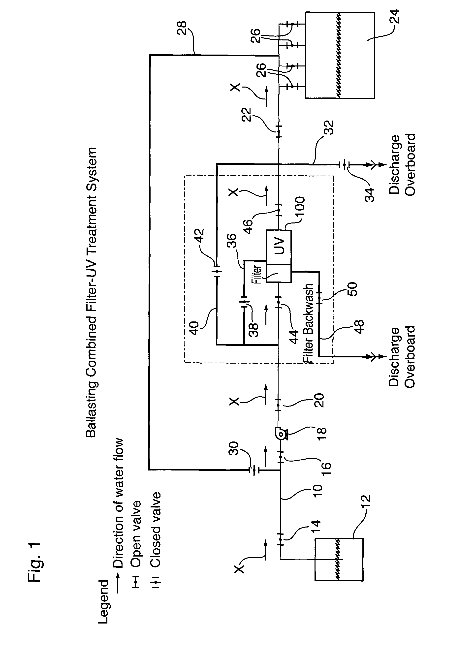
[0130]In a first embodiment, the method comprises the steps of:

[0131]cutting the first plumbing line;

[0132]splitting an upstream cut portion of the first plumbing line into a main plumbing line and a bypass plumbing line;

[0133]connecting the main plumbing line to the first fluid inlet;

[0134]connecting the bypass plumbing line to the second fluid inlet;

[0135]connecting a downstream cut portion of the first plumbing line to the fluid outlet;

[0136]installing the first valve element in the main plumbing line upstream of the fluid treatment system; and

[0137]installing the second valve element in the bypass line upstream of the fluid treatment system.

second embodiment

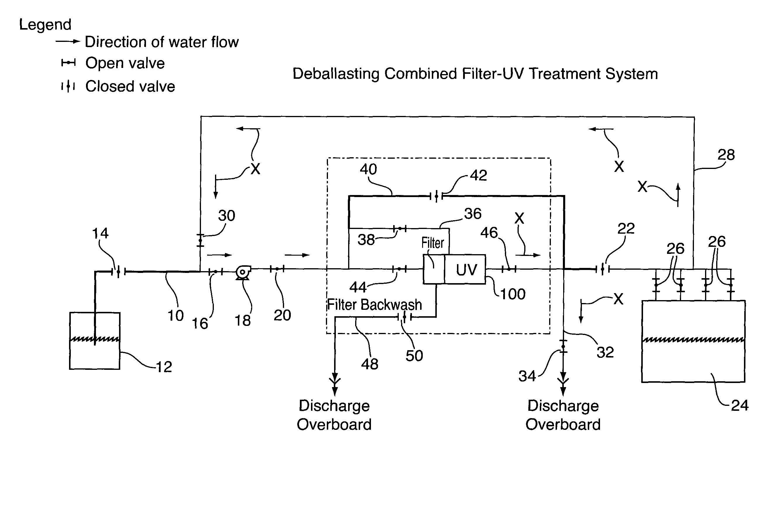
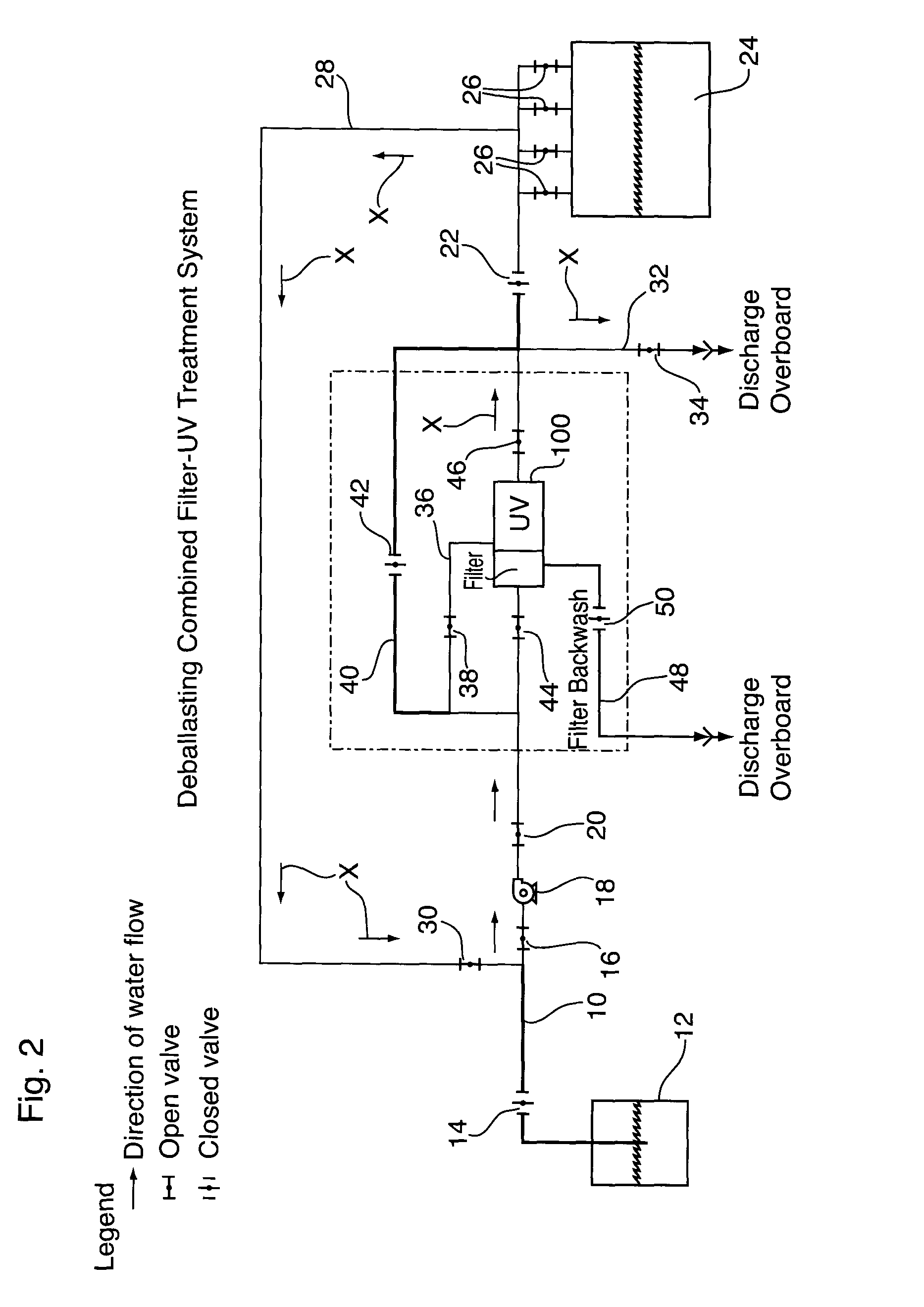
[0138]In a second embodiment where the fluid separation section of the fluid treatment system comprises a backwash element, the method comprises the steps of:

[0139]cutting the first plumbing line;

[0140]splitting an upstream cut portion of the first plumbing line into a main plumbing line and a bypass plumbing line;

[0141]connecting the main plumbing line to the first fluid inlet;

[0142]connecting the bypass plumbing line to the second fluid inlet;

[0143]connecting a downstream cut portion of the first plumbing line to the fluid outlet;

[0144]connecting discharge portion of the backwash element to a overboard discharge plumbing line;

[0145]installing the first valve element in the main plumbing line upstream of the fluid treatment system;

[0146]installing the second valve element in the bypass line upstream of the fluid treatment system; and

[0147]installing the backwash valve element in the overboard discharge plumbing line.

third embodiment

[0148]In a third embodiment where it is desired to be able to bypass the fluid treatment system entirely, the method comprises the steps of:

[0149]cutting the first plumbing line;

[0150]splitting an upstream cut portion of the first plumbing line into a main plumbing line, a first bypass plumbing line and a second bypass plumbing line;

[0151]connecting the main plumbing line to the first fluid inlet;

[0152]connecting the first bypass plumbing line to the second fluid inlet;

[0153]connecting a downstream cut portion of the first plumbing line to the fluid outlet;

[0154]connecting the second bypass plumbing line to the downstream cut portion of the first plumbing line

[0155]installing the first valve element in the main plumbing line upstream of the fluid treatment system;

[0156]installing the second valve element in the first bypass line upstream of the fluid treatment system; and

[0157]installing the third valve element in the second bypass line.

[0158]With respect to each of the above-mentio...


PUM

PropertyMeasurementUnit
Flow rateaaaaaaaaaa

Abstract

There is described a fluid treatment system that is particularly well suited for treating ballast water on a shipping vessel. The present fluid treatment system is characterized by having two general modes of operation. A so-called ballasting mode and a so-called deballasting mode. In the ballasting mode, water is pumped from the sea or other body of water in which the shipping vessel is located to a ballast fluid inlet in the present fluid treatment system. Thereafter, it passes through the filter separation and radiation treatment sections in the fluid treatment zone of the fluid treatment system. Next, the fluid exits the fluid outlet of the fluid treatment system and it is pumped to one or more ballast tanks that are located on the shipping vessel. In the deballasting mode, water contained in the ballast tank(s) is pumped to a deballasting fluid inlet of the fluid treatment system after which it is treated in the radiation section only—i.e., in the deballasting mode, water substantially bypasses the fluid separation section of the fluid treatment system. Next, the treated fluid exits the fluid outlet of the fluid treatment system and is discharged overboard the shipping vessel. A valve system is used to switch between ballasting mode and deballasting mode.

Description

CROSS-REFERENCE TO RELATED APPLICATION[0001]The present application claims the benefit under 35 U.S.C. §119(e) of provisional patent application Ser. No. 61 / 411,679, filed Nov. 9, 2010, the contents of which are hereby incorporated by reference.BACKGROUND OF THE INVENTION[0002]1. Field of the Invention[0003]In one of its aspects, the present invention relates to a fluid treatment system. More particularly, the present invention relates to a fluid treatment system for treatment of liquids such as water. Even more particularly, the present invention relates to a fluid treatment system for treatment of water such as ballast water from marine vessels. In another of its aspects, the present invention relates to a method for installing a fluid treatment device in a shipping vessel.[0004]2. Description of the Prior Art[0005]Fluid treatment systems are generally known in the art. More particularly, ultraviolet (UV) radiation fluid treatment systems are generally known in the art. Early trea...

Claims


Application Information

Patent Timeline
IPC IPC(8): C02F1/32C02F1/00B63J4/00
CPCB63J4/002C02F2103/008C02F1/325C02F2201/3227C02F2303/16C02F2301/043C02F1/004Y10T29/49826
Inventor DACOSTA, MATTHEWFRASER, JIMLATIMER, GLEN E.
Owner TROJAN TECH
Why Eureka
Try Eureka