
Wire-array pressure and movement sensor

Inactive Publication Date: 2014-02-13
GOLDBAUM HAROLD J
View PDF3 Cites 10 Cited by
  • Summary
  • Abstract
  • Description
  • Claims
  • Application Information

AI Technical Summary

Benefits of technology

The invention is a pressure sensor that can sense pressure and movement in "X" and "Y" coordinates. It can be used as a flat computer touchpad or a user identity device. The sensor is integrated into a flexible upper housing segment of a computer touchpad or can be attached to a computer touchpad. It can be detached and used with a laptop or desktop computer. The sensor is simple yet effective and provides enhanced functionality.

Problems solved by technology

Further, while most will register a static pressure and the movement in the device's plane, few are capable of registering the pressure and variation thereof at any point in the plane.
Those configurations having this capability are significantly more expensive.
Use of the touchpad requires repetitive finger movement, leading to a somewhat difficult manner of use.
In addition, should the user's finger be slightly moist, the performance of the sensors in the pad is degraded.
While this placement accommodates both right-handed and left-handed users, this compromise position is not particularly comfortable for either to use, since most touchpad users are accustomed to having the mouse located on a particular side of the keyboard based on whether they are right-handed or left-handed.
Thus, users of notebook computers who find the touchpad's bothersome and inefficient resort to the use of an external user input device, such as a mouse, a trackball, and the like, even though its volume is cumbersome with relation to the size of the computer.
Manufacturers of mice have reacted to his situation by developing smaller desktop mice and, while these mice have somewhat alleviated the problem of size, not only is the user still required to carry a separate piece of equipment, but also a flat space may not be available, forcing the user to use the bothersome touchpad.
It is now known that many users of current art desktop mice may develop a medical problem from such grasping, which may lead to physical discomfort, carpal tunnel syndrome, or other repetitive motion injuries.
These problems have led to the introduction of different input devices, for example: (1) ergonomic mice, which strive to alleviate the “grasping” problem; (2) a flat wireless computer touchpad, which is capable of being stored in the PC Card slot of a notebook computer, but which is not fully functional.
However, that device comprises many moving parts and is mechanically complex; it is thus prone to defects, wear and failure of such parts, and is also prone to being fouled by dirt and dust.
Use of a credit card when making purchases on the Internet is particularly prone to fraud.
A signature pad does not verify the signature of the person signing.
As there is no verification of the signature, there is no assurance that the signer is the authorized user of the credit card.
In some retail establishments where there is no signature pad, the purchaser signs a slip of paper accepting the charge but, again, there is no assurance that the person signing is in fact the owner of account associated with the financial card.
However there is no assurance that the user is, in fact, an authorized user; the PIN may have become known to a person who stole the debit card, and obtained knowledge of the PIN.
While the verification error rate of these programs is very low, and the ability of these programs to recognize signatures is constantly improving, the system is not error free.
In this age of global business, communications and electronic documents, signature recognition devices are extremely important, and a verification error could be extremely costly.
Though such devices obviously do provide a certain level of security, it is obvious that a high level of security requires longer coded series.
The longer the code, the higher the level of difficulty for the user to remember.
As the level of difficulty increases, the likelihood that the user would record the security code in a manner other than memory also increases.
Further, an unauthorized user may gain access to the input code series by surreptitious observation of the authorized user's entry of the input code series, or by other known and quite accessible means.
Combination safes have a limited security level and are known to be easily defeated by a technology equipped unauthorized user.
These are rather expensive devices and, while their error rate is very low, they also have their shortcomings.

Method used


Image

  • Wire-array pressure and movement sensor
  • Wire-array pressure and movement sensor
  • Wire-array pressure and movement sensor

Examples


Embodiment Construction

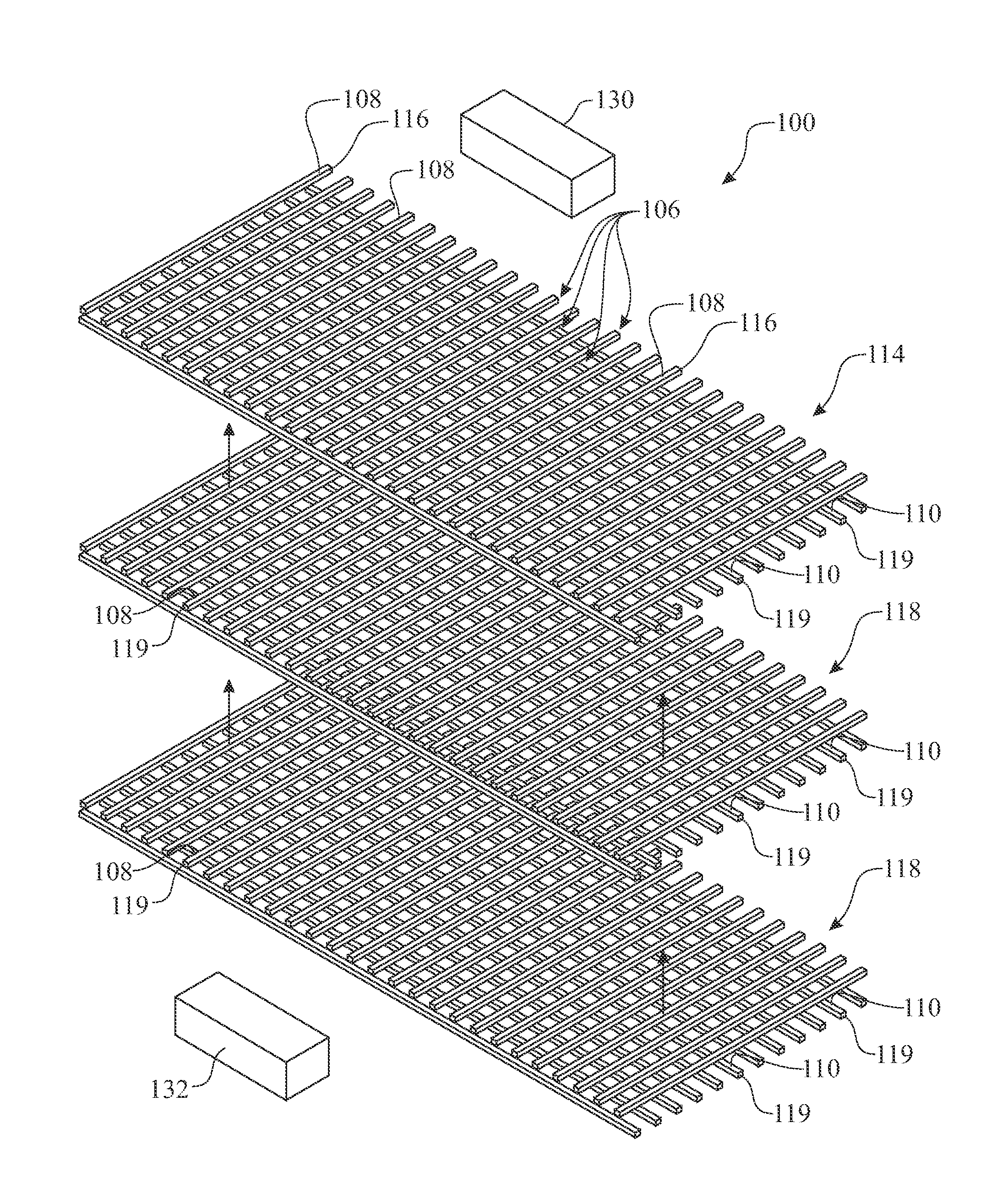
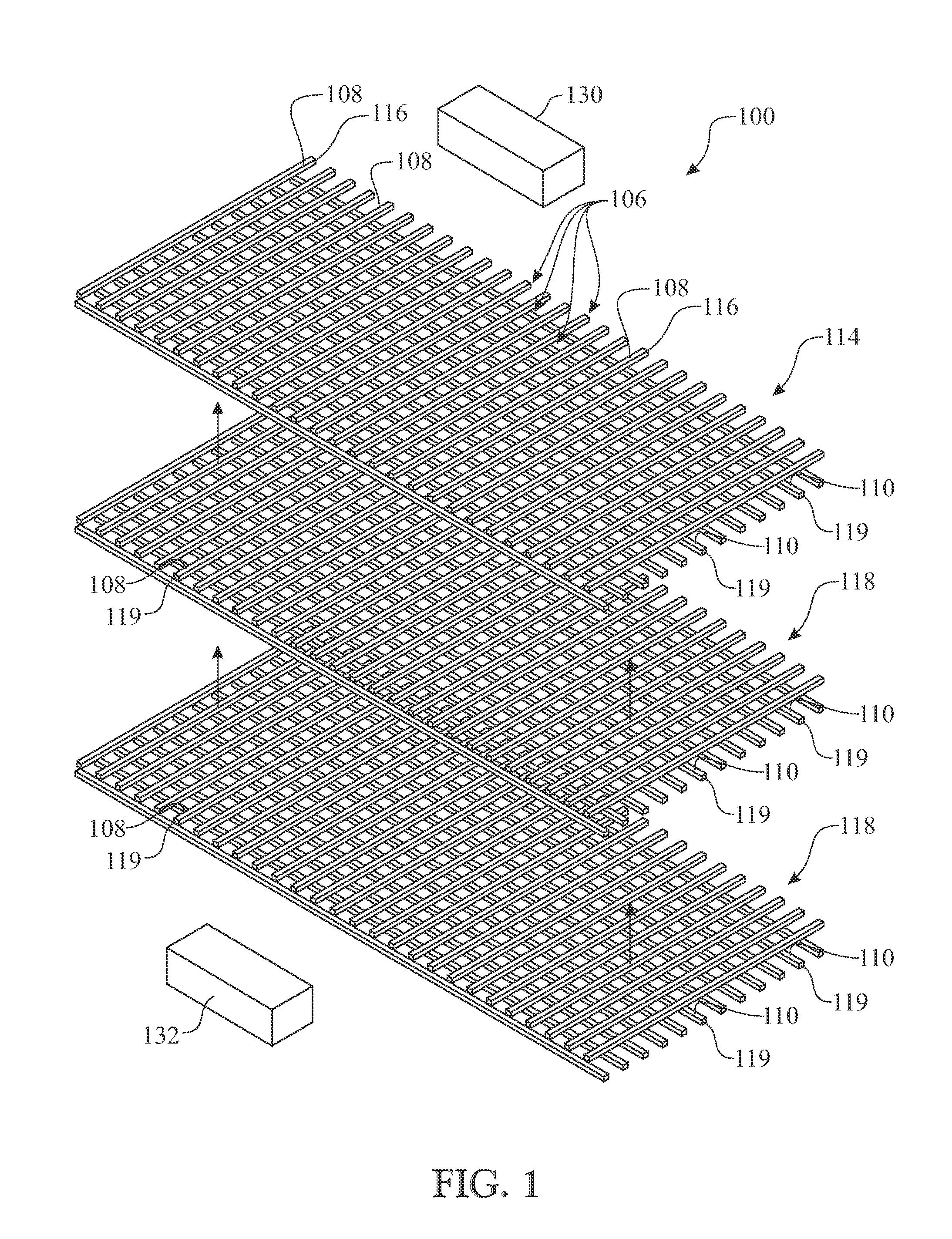
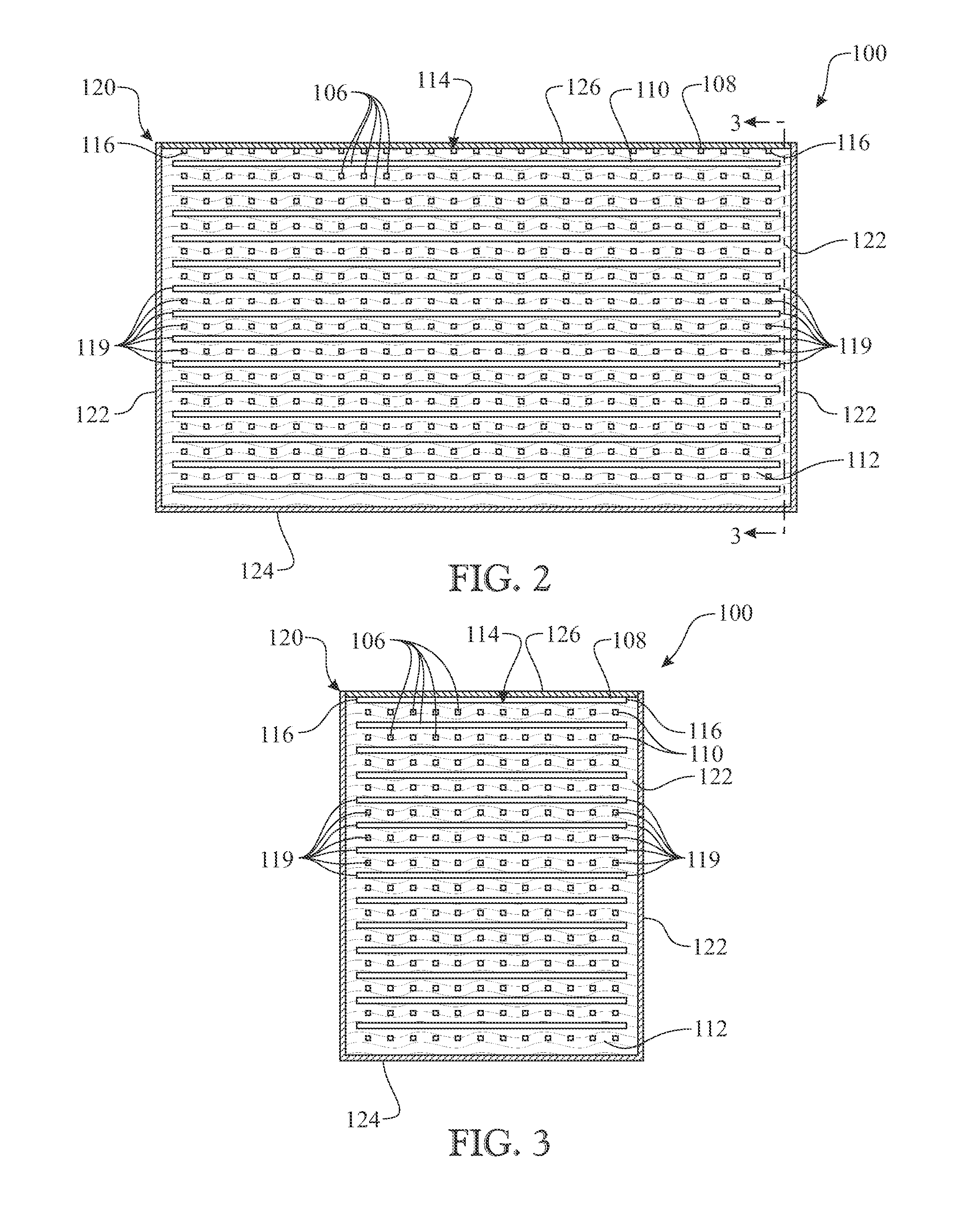
[0067]The following detailed description is merely exemplary in nature and is not intended to limit the described embodiments or the application and uses of the described embodiments. As used herein, the word “exemplary” or “illustrative” means “serving as an example, instance, or illustration.” Any implementation described herein as “exemplary” or “illustrative” is not necessarily to be construed as preferred or advantageous over other implementations. All of the implementations described below are exemplary implementations provided to enable persons skilled in the art to make or use the embodiments of the disclosure and are not intended to limit the scope of the disclosure, which is defined by the claims. For purposes of description herein, the terms “upper”, “lower”, “left”, “rear”, “right”, “front”, “vertical”, “horizontal”, and derivatives thereof shall relate to the invention as oriented in FIG. 1. Furthermore, there is no intention to be bound by any expressed or implied theo...


PUM


Abstract

A multilayer wire array having an upper layer having a series wires arranged in an equally spaced, parallel relationship and a series of internal layers located in a spatial arrangement below the upper layer. Each internal layer is similar to the upper layer, wherein each internal layer is oriented preferably perpendicularly to the adjacent layers. The upper layer is provided in electrical connectivity with a power source. Each subsequent layer is provided in electrical communication with a sensing device. Pressure is applied to the wire array, wherein the pressure distorts the layers causing electrical communication between contacting wires. The connectivity provides an output that is sensed by the sensing device and subsequently analyzed to determine the location and any respective movement of the pressure applied to the array. The output data can be used as a pointing device for a computer, a user identity device, and a security device.

Description

CROSS REFERENCE TO RELATED APPLICATIONS[0001]This United States Non-Provisional Patent Application claims the benefit of U.S. Provisional Patent Application Ser. No. 61 / 555,906, filed on Nov. 4, 2011, which is incorporated in its entirety herein by reference.FIELD OF THE INVENTION[0002]The present invention relates to a pressure sensor utilizing an array of wires, and more specifically, the array of wires comprising a series of layers, each layer having a plurality of wire segments configured in a substantially parallel arrangement, the array being capable of determining both “X” and “Y” coordinates as well as pressure applied to a user interface.BACKGROUND OF THE INVENTION[0003]There are many types of pressure sensors that exist in many forms in current art; they generally measure the pressure of air or liquids. Those of which are flat generally rely on a plurality of piezoelectric resistive elements assembled into an array. The number and density of the piezoelectric resistive ele...

Claims


Application Information

Patent Timeline
IPC IPC(8): G01D7/00G06F3/041
CPCG06F3/03547G01L1/205G06F3/04144
Inventor GOLDBAUM, HAROLD J.
Owner GOLDBAUM HAROLD J
Learn More