Switching power supply device control circuit and switching power supply

a power supply device and control circuit technology, applied in the direction of electric variable regulation, process and machine control, instruments, etc., can solve the problems of increasing the cost and size of the power supply device, and the current size is no longer able to coincide, so as to reduce emi noise, eliminate unnecessary margins in the rated current, and avoid increasing the circuit scale

Active Publication Date: 2014-02-13
FUJI ELECTRIC CO LTD
View PDF7 Cites 21 Cited by
  • Summary
  • Abstract
  • Description
  • Claims
  • Application Information

AI Technical Summary

Benefits of technology

[0064]According to embodiments of the invention, it is possible to realize a function of regulating the overcurrent protection level without increasing the circuit scale, even when using an oscillator having a modulation period (idle period) in the oscillation waveform.
[0065]Consequently, it is possible, in an IC that controls a power supply circuit (flyback) and has a function of modulating frequency using a modulation period (idle period) for reducing EMI noise, to turn off a MOSFET at the same overcurrent level, regardless of the input voltage.
[0066]Further, by turning off a switch at the same overcurrent level, it is possible to eliminate an unnecessary margin in the rated current of the switch, inductor, and transformer, and thus possible to realize a reduction in the cost and size of the power supply device.
[0067]The heretofore described and other objects, characteristics, and advantages of the invention will be made clear by the attached drawings representing an embodiment preferred as an example of the invention, and by the following related description.
[0068]Additional aspects and / or advantages will be set forth in part in the description which follows and, in part, will be apparent from the description, or may be learned by practice of the invention.

Problems solved by technology

However, when the duty cycle (on-state time ratio=on-state time duration / switching cycle) of the MOSFET 17 becomes too long, the sizes of the current are no longer able to coincide, and the condition of the current flowing through the MOSFET 17 fluctuates with each switching cycle.
Consequently, the heretofore known flyback power supply whose PWM is to be controlled is such that it is necessary to increase the rated current of the MOSFET 17, transformer T, and the like, which is a factor leading to an increase in the cost and size of the power supply device.

Method used


Image

  • Switching power supply device control circuit and switching power supply
  • Switching power supply device control circuit and switching power supply
  • Switching power supply device control circuit and switching power supply

Examples


Embodiment Construction

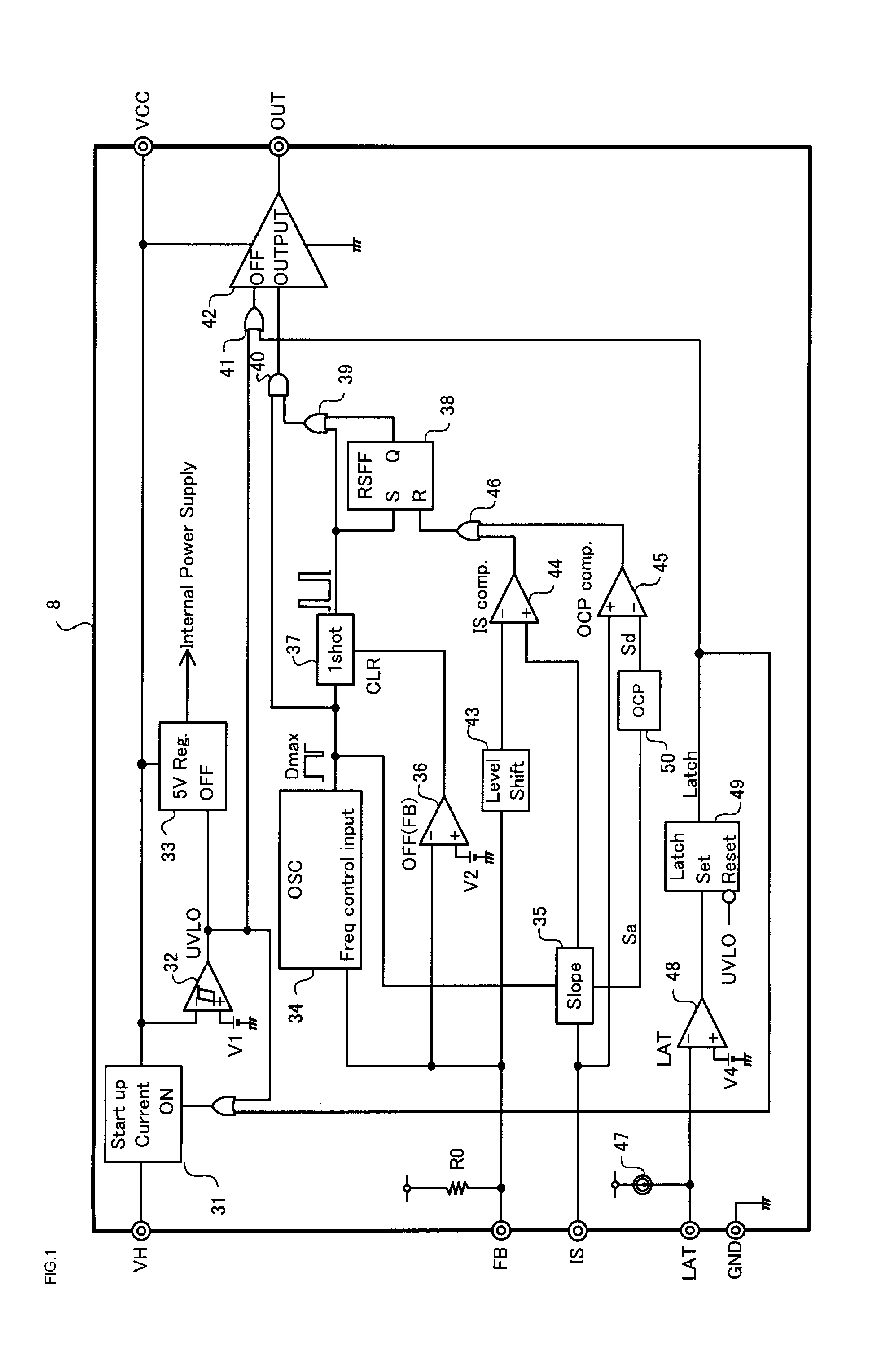
[0083]Hereafter, referring to the drawings, a description will be given of an embodiment of the invention. FIG. 1 is a block diagram showing a configuration of a switching power supply control circuit according to the embodiment.

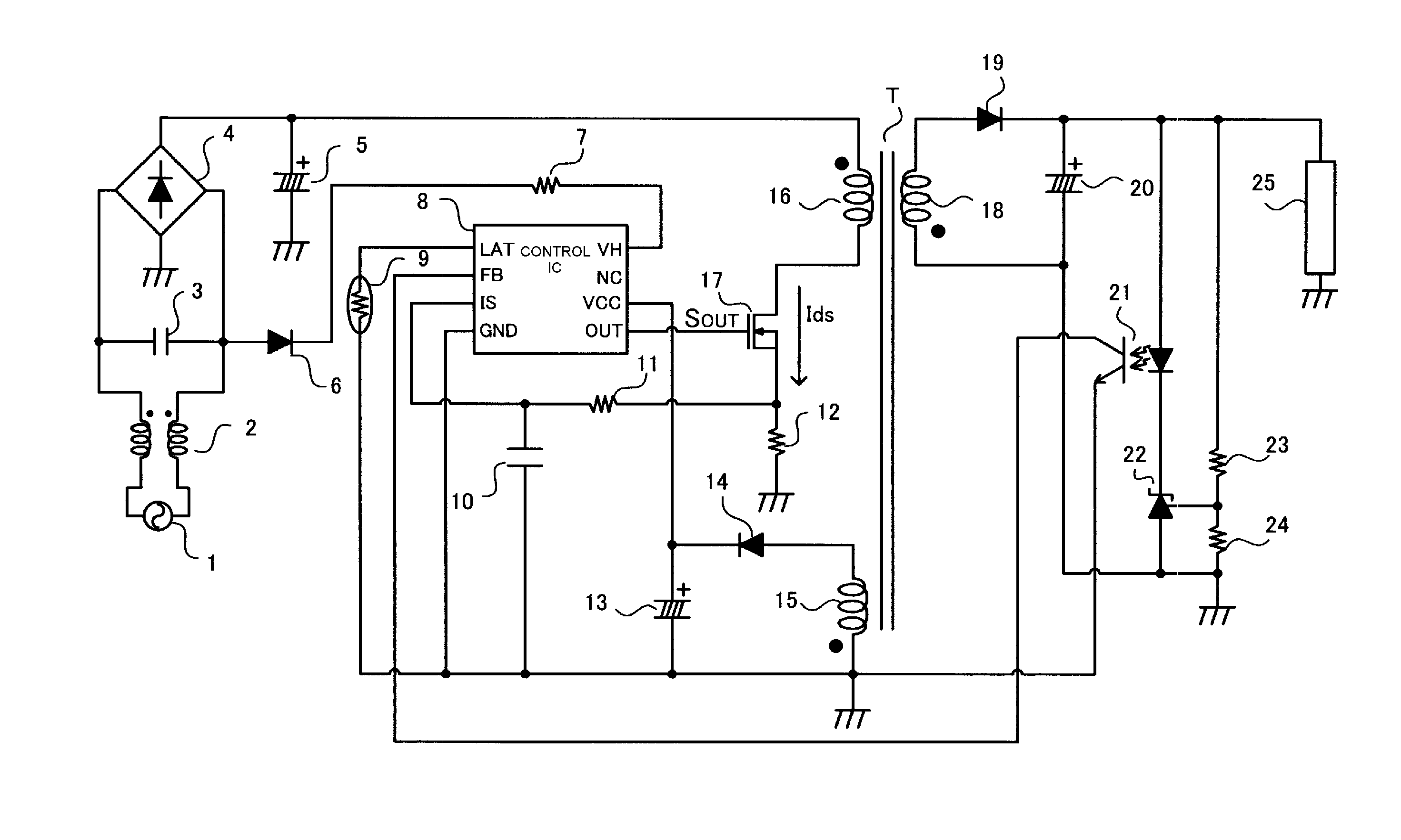
[0084]A control IC 8 configuring the switching power supply control circuit has basically the same configuration as a related PWM controlling control IC 8 previously described in FIG. 6. The control IC 8, based on voltage from an AC input 1, controls a flyback power supply (refer to FIG. 5) that generates a constant output voltage. Also, a current detecting sense resistor 12 for converting the voltage of current flowing through a MOSFET 17, shown in FIG. 5, an IS terminal that detects a converted voltage signal, and an OCP comparator 45 for detecting an overcurrent in the control IC 8 configure an overcurrent protection circuit for detecting overcurrent.

[0085]A description will be given of portions in FIG. 1 differing from a heretofore known switching power ...


PUM


Abstract

A switching power supply device control circuit and switching power supply can combat fluctuation due to the input voltage in the peak current of a switching element, even when using an oscillator. A control IC is connected to a switching element and to a current detecting resistor, and controls the switching element, the control IC being configured of an OCP comparator that detects an overcurrent with respect to a load, an overcurrent level setting circuit that corrects a fluctuation occurring in the peak current of the switching element in response to the output voltage from the AC input, an oscillator having a frequency modulating function whereby the switching frequency with respect to the switching element can be modulated, and a slope compensation circuit that generates a slope compensation signal increasing monotonically in proportion to the time from the start of each cycle of an oscillating signal of the oscillator.

Description

CROSS-REFERENCE TO RELATED APPLICATIONS[0001]This application is a continuation application, filed under 35 U.S.C. §111(a), of International Application PCT / JP2012 / 063170 filed on May 23, 2012, and claims foreign priority benefit of Japanese Patent Application 2011-154075 filed on Jul. 12, 2011 in the Japanese Patent Office, the disclosures of both of which are incorporated herein by reference.BACKGROUND[0002]1. Field[0003]Embodiments of the present invention relate to a control circuit and switching power supply of a flyback type switching power supply device that converts the voltage of an AC input that turns a switching element on and off into a predetermined direct current voltage and supplies the voltage to a load, and in particular, relate to a control circuit and switching power supply of a switching power supply device that can combat fluctuation due to the voltage value of the AC input in an overcurrent peak current flowing through the switching element.[0004]2. Description...

Claims


Application Information

Patent Timeline
Patent Type & Authority Applications(United States)
IPC IPC(8): H02M3/335H02M1/00
CPCH02M2001/0025H02M3/33507H02M3/33523H02M1/0025H02H9/025
Inventor SUGAWARA, TAKATOYAMANE, HIROKI
Owner FUJI ELECTRIC CO LTD
Why Eureka
Try Eureka