Modular Electric Wall Heater

a heater and module technology, applied in the field of heater technology, can solve the problems of inefficiency of assembly line production, inconvenient maintenance, and inconvenient maintenance, and achieve the effects of reducing maintenance costs, improving production efficiency, and saving space and transportation costs

Inactive Publication Date: 2014-02-13
CHU HAK KEE
View PDF11 Cites 21 Cited by
  • Summary
  • Abstract
  • Description
  • Claims
  • Application Information

AI Technical Summary

Benefits of technology

[0003]The objective of this invention focus on the issues with the current wall heater that are generally large in size and weight, excess assembly components and difficulty in disassemble when repairing that bring high production and manpower costs in the production, transportation, installation and maintenance of the wall heaters. The objective of present invention is to provide a modular electric wall heater with low production costs, easier to transport and disassemble for better maintenance and repair. As a result, manufacturer can achieve higher production efficiency and for the user, to reduce cost in maintain and repair the heater unit.
[0010]The beneficial effects of the present invention are that: the various heater components can be independently produce and delivered, increases production efficiency, and to save space and transportation costs by disassembling the heater unit during transportation. In addition, repairing is made simpler as each component can be readily and easily replaced. Furthermore, as the low pressure and high pressure are centralized enclosed individually in the respective main box, greatly improving the safety of operation.

Problems solved by technology

Because of scattered layout and staggered between the various parts of the heater, and the high-pressure part of the product components and the low pressure part components widely distributed and messy results in excess use of connection parts, wire terminals, terminal caps, and screws.
Thus making the whole assembly line production inefficient and requires more manpower and specialized equipment to assembly or disassembles high transportation costs of product packaging, maintenance and replacement is more complicated.

Method used


Image

  • Modular Electric Wall Heater
  • Modular Electric Wall Heater
  • Modular Electric Wall Heater

Examples


Embodiment Construction

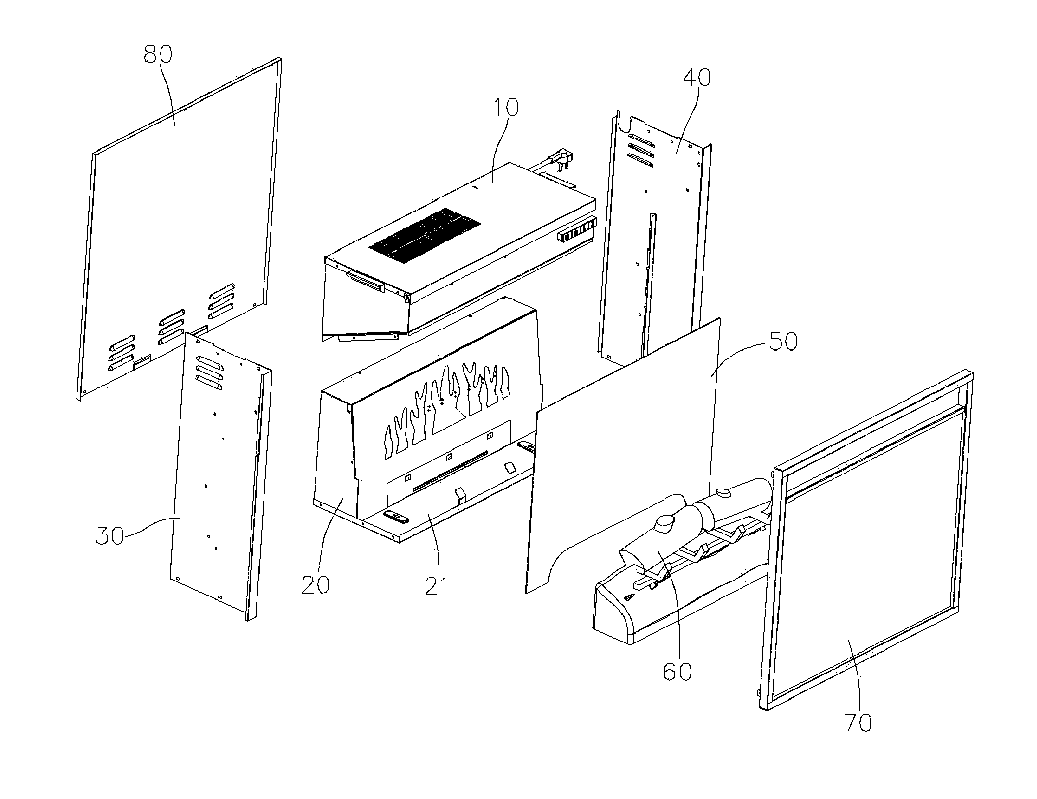
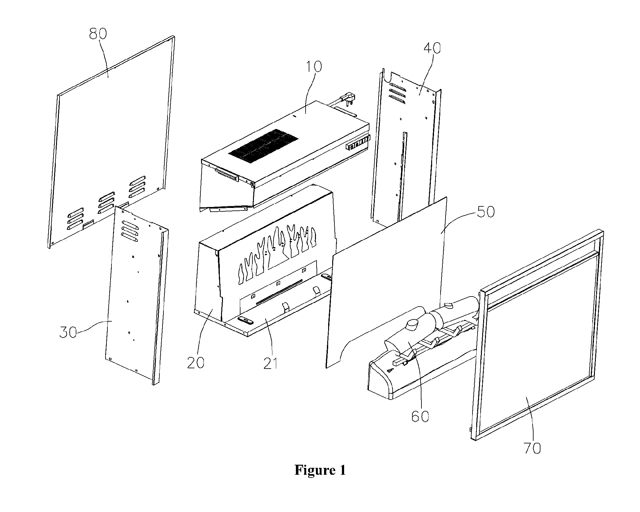
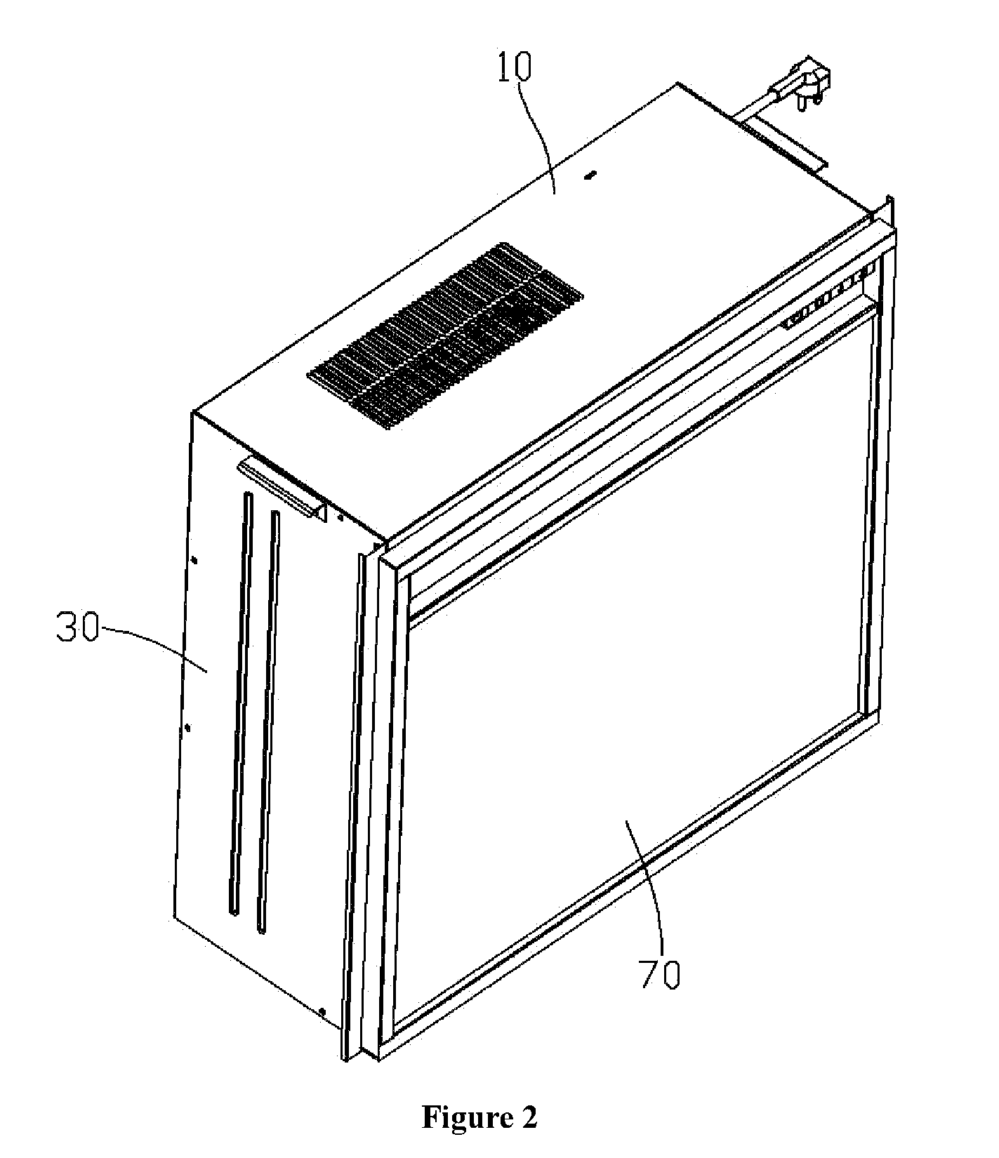
[0018]As shown in FIG. 1 through FIG. 7: the present invention of modular electric wall heater (heater) comprises an upper main box component 10, a lower main box component 20, a left side panel component 30, a right side panel component 40, a flame simulator component 50, a fake ashes component 60, a front panel component 70 and a rear panel component 80, wherein, the upper main box component 10 is a closed structure and enclosing, at least, a heater 11, a fan motor 12, an air outlet channel 13 and enclosing other elements not shown in the drawings: a main control circuit board, a control key board, a receiver, a power cord or power cord slot, a Negative Temperature Coefficient Thermistor (NTC), a shell box, fan motor seat, an air filter or an air outlet. The lower main box component 20 can also be a closed structure, enclosing, at least, a bottom panel 21, a flame PCB light strip 22, a blue light PCB light strip 23, a gray PCB light strip 24, a screen film 25 imprint with flame de...


PUM


Abstract

A modular electric wall heater comprises an upper main box components, a lower main box component, a left side panel component, a right side panel component, a flame simulator component, a fake ash component, a front panel component, and a rear panel component; the left side panel component and the right side panel component connect with the upper main box component and the lower main box component to form an enclosure; the flame simulator component situates inside of the enclosure and is connected with the left side and right side panel component; the ashes component situates inside of the enclosure, and on the top of the and connect to a bottom panel of the lower main box component, the frontal panel component is situate on the frontal opening of the enclosure and the rear panel component is situate on the rear opening of the enclosure.

Description

FIELD OF THE INVENTION[0001]The present invention relates generally to a heater technology, especially a modular electric wall heater.BACKGROUND OF INVENTION[0002]Currently in the electric heater market, the electric heater mainly comprises electronic components (heater, blower, and reflective article motor), LED flame simulator, outer shell assembly and other assembly components. Because of scattered layout and staggered between the various parts of the heater, and the high-pressure part of the product components and the low pressure part components widely distributed and messy results in excess use of connection parts, wire terminals, terminal caps, and screws. Thus making the whole assembly line production inefficient and requires more manpower and specialized equipment to assembly or disassembles high transportation costs of product packaging, maintenance and replacement is more complicated.SUMMARY OF THE INVENTION[0003]The objective of this invention focus on the issues with th...

Claims


Application Information

Patent Timeline
Patent Type & Authority Applications(United States)
IPC IPC(8): F24H3/04F24H9/02
CPCF24H9/02F24H3/0417F24B1/1808
Inventor CHU, HAK KEE
Owner CHU HAK KEE
Why Eureka
Try Eureka