Fuel cell system and method for deactivating fuel cell system

Active Publication Date: 2014-02-13
HONDA MOTOR CO LTD
View PDF1 Cites 0 Cited by
  • Summary
  • Abstract
  • Description
  • Claims
  • Application Information

AI Technical Summary

Benefits of technology

The present invention relates to a method and system for deactivating a fuel cell system. The technical effects of this invention include reducing oxygen concentration within the cathode system of the fuel cell by consuming the remaining oxygen through low electric-power generation prior to oxygen-consumption electric-power generation. This is achieved by controlling the electric-power generation in the fuel cell to cause a net output to be a negative value, which results in a reduction of the state of charge in the electricity storage device. The system includes a fuel cell, auxiliary device, electricity storage device, stop switch, and controller. The controller is responsible for performing low electric-power generation and compensating for a negative net output by discharging electricity from the electricity storage device before initiating oxygen-consumption electric-power generation.

Problems solved by technology

The high potential state at the cathode is known to cause deterioration in a solid polymer electrolyte membrane that constitutes the fuel cell.

Method used


Image

  • Fuel cell system and method for deactivating fuel cell system
  • Fuel cell system and method for deactivating fuel cell system
  • Fuel cell system and method for deactivating fuel cell system

Examples


first embodiment

[0038]Next, a method for deactivating a fuel cell system according to a first embodiment will be described.

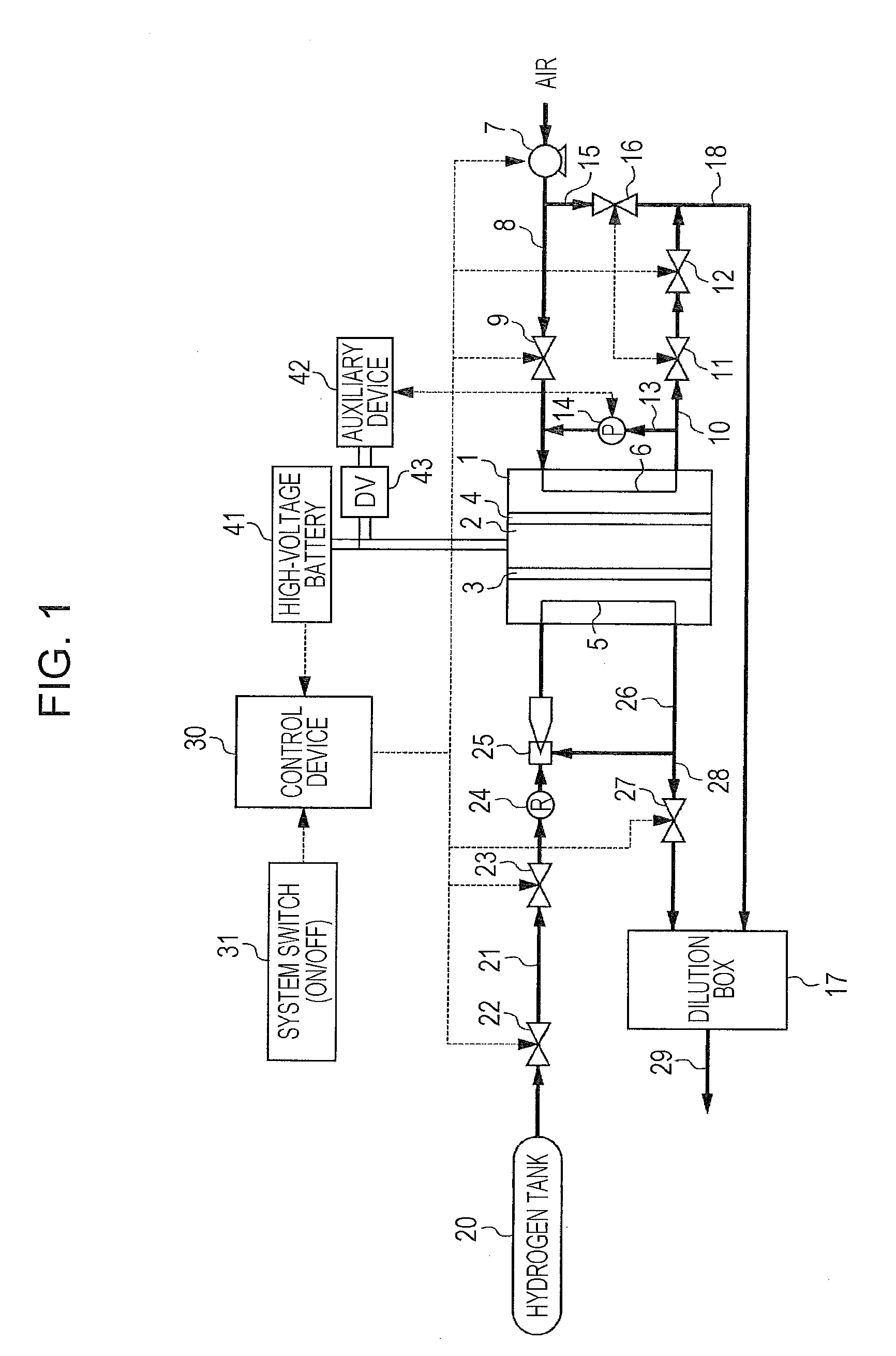
[0039]An amount of electric power generated in the fuel cell 1 will be defined as a gross output W1, a consumed electric power by the auxiliary device 42 actuated for obtaining the gross output W1 will be defined as W2, and an electric power obtained by subtracting the consumed electric power W2 of the auxiliary device 42 from the gross output W1 of the fuel cell 1 will be defined as a net output W3 of the fuel cell 1 (W3=W1−W2).

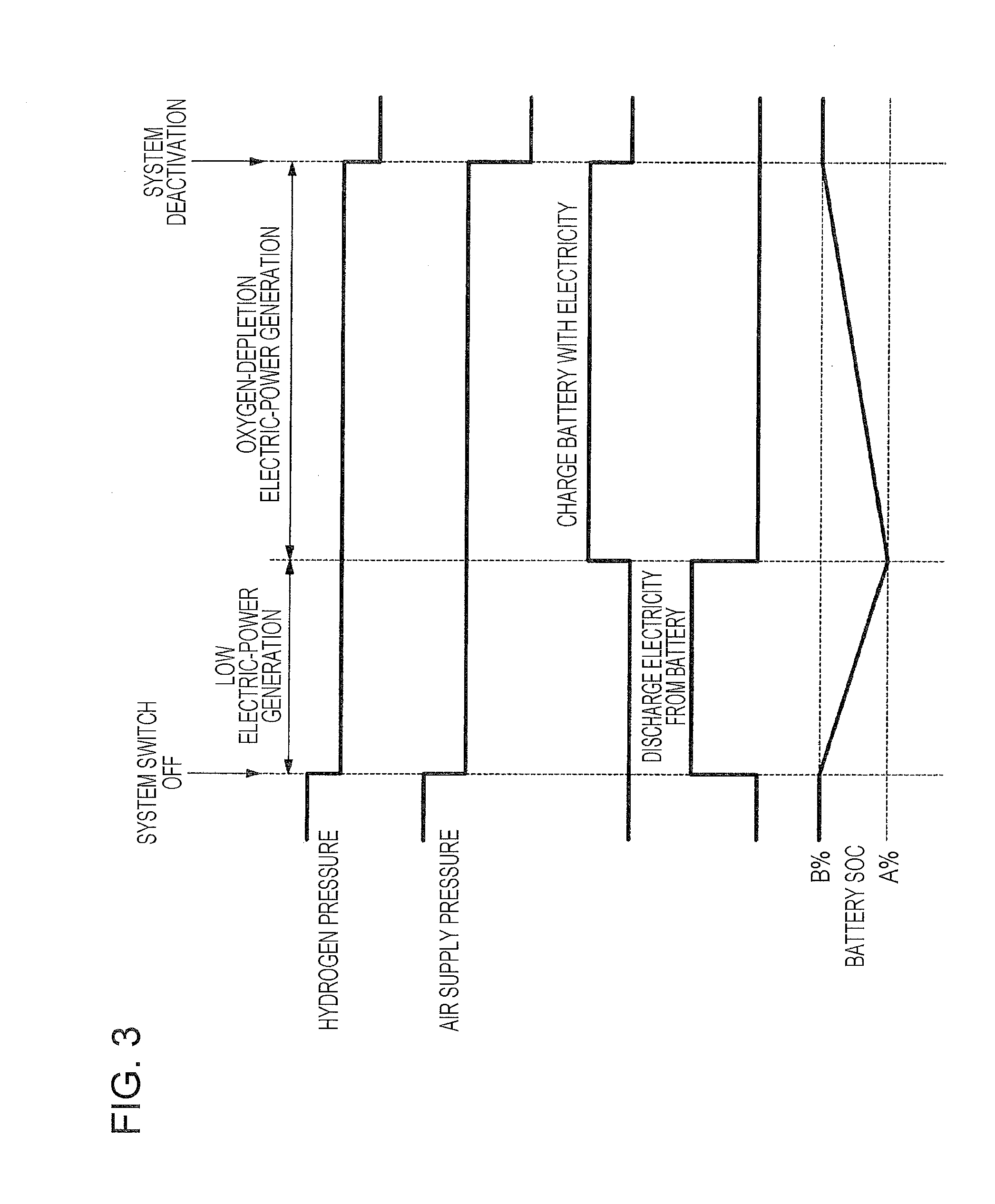
[0040]In the cathode circulation electric-power generation performed as the oxygen-consumption electric-power generation, the supply of reaction gases (i.e., hydrogen and air) is controlled such that the net output W3 becomes a positive value. Therefore, during the cathode circulation electric-power generation performed as the oxygen-consumption electric-power generation, the net output W3, which is a positive value, is stored into the high-voltage batt...

second embodiment

[0081]Next, a method for deactivating a fuel cell system according to a second embodiment of the present application will be described.

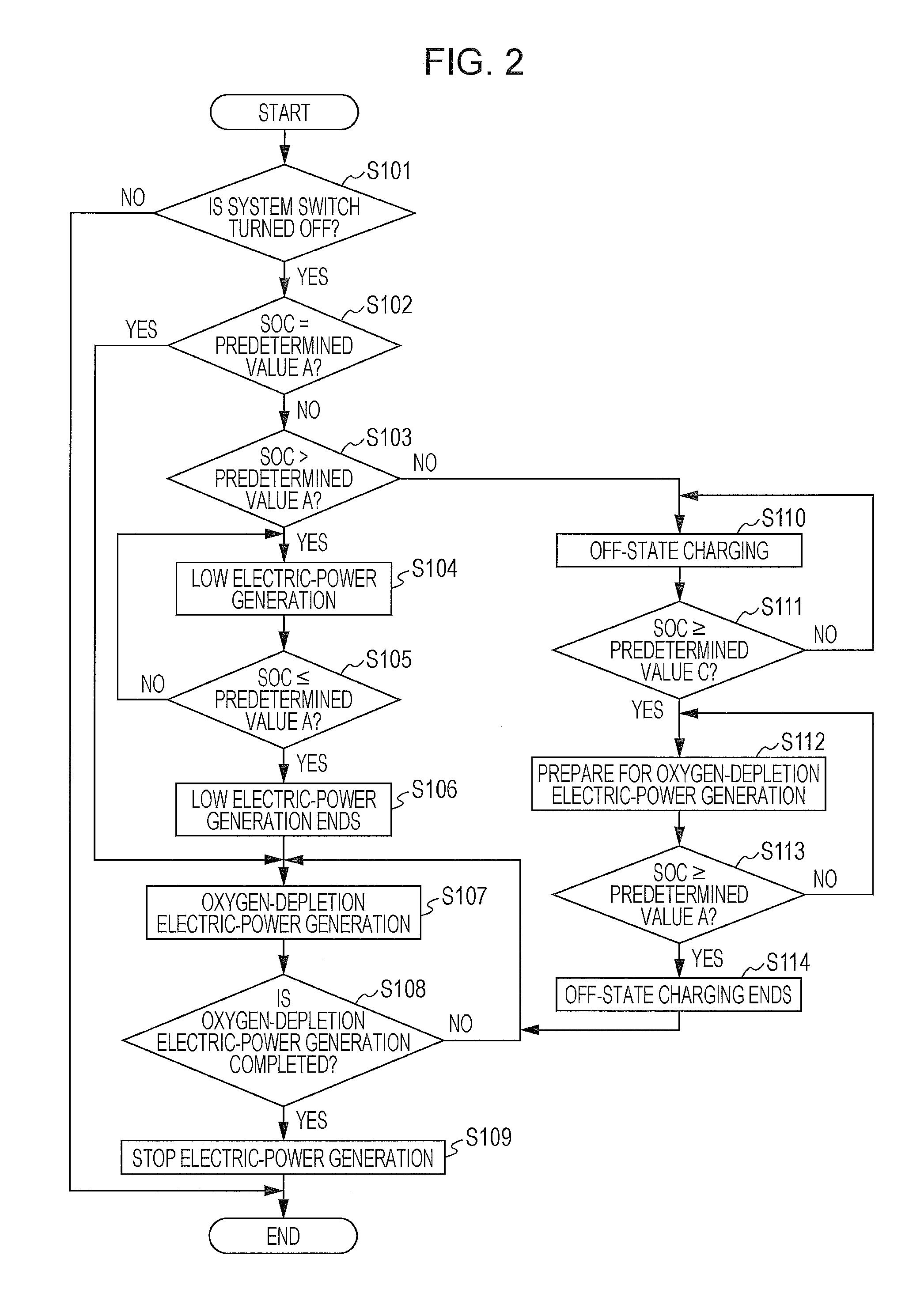
[0082]In the method for deactivating the fuel cell system according to the first embodiment, the net output W3 of the fuel cell 1 is constantly a positive value in the cathode circulation electric-power generation performed as the oxygen-consumption electric-power generation. Therefore, it is necessary to ensure the required free capacity in the high-voltage battery 41 before commencing the oxygen-consumption electric-power generation. In order to achieve this, low electric-power generation is performed so as to reduce the SOC in the high-voltage battery 41 to the predetermined value A.

[0083]In contrast, in the second embodiment, the cathode circulation electric-power generation performed as the oxygen-consumption electric-power generation is based on variable electric-power generation so that the low electric-power generation in the first embodiment...


PUM


Abstract

In a method for deactivating a fuel cell system, low electric-power generation is performed prior to oxygen-consumption electric-power generation in a case where a state of charge in an electricity storage device provided in the fuel cell system is larger than a predetermined value when a stop switch provided in the fuel cell system is operated. After the state of charge in the electricity storage device is reduced to the predetermined value by compensating for a negative net output by discharging electricity from the electricity storage device, the oxygen-consumption electric-power generation in which oxygen remaining in a cathode system of the fuel cell is consumed to reduce oxygen concentration within the cathode system is performed.

Description

CROSS-REFERENCE TO RELATED APPLICATIONS[0001]The present application claims priority under 35 U.S.C. §119 to Japanese Patent Application No. 2012-175954, filed Aug. 8, 2012, entitled “Method for Deactivating Fuel Cell System.” The contents of this application are incorporated herein by reference in their entirety.BACKGROUND OF THE INVENTION[0002]1. Field of the Invention[0003]The present disclosure relates to a fuel cell system and a method for deactivating the fuel cell system.[0004]2. Discussion of the Background[0005]A fuel cell has an anode and a cathode and generates electric power by being supplied with hydrogen (i.e., fuel gas) to the anode and air containing oxygen (i.e., oxidant gas) to the cathode. When the electric-power generation in the fuel cell is to be stopped, if the oxygen remains in the cathode system, the cathode is known to become in a high potential state when hydrogen is supplied to the anode at the time of subsequent activation. The high potential state at th...

Claims


Application Information

Patent Timeline
IPC IPC(8): H01M8/04
CPCH01M8/04223H01M8/04955H01M2008/1095H01M2250/30H01M8/04228H01M8/04303Y02B90/10Y02E60/50
Inventor KIKUCHI, GOWAKE, CHIHIRO
Owner HONDA MOTOR CO LTD
Why Eureka
Try Eureka