
Hair dryer attachment

Active Publication Date: 2014-02-20
TORRES SERAFINO +1
View PDF7 Cites 6 Cited by
  • Summary
  • Abstract
  • Description
  • Claims
  • Application Information

AI Technical Summary

Benefits of technology

This patent describes a device and system for blow drying hair. The device includes a flexible coupling sleeve that can be easily engaged with different sized blow driers. The sleeve has one end that attaches to a barrel of the blow dryer and the other end that attaches to a nozzle. The nozzle end attachments, such as a brush or sponge, can be easily removed and replaced to apply moisture, lotions, or serums to the hair and then quickly dry it without needing to switch hands. The technical effects of this device and system include a wider range of amenable blow dryers, easier application of moisture, and faster and more efficient drying.

Problems solved by technology

As could be imaged, there are many drawbacks with such a tedious process.
First, when applying lotions and serums to the hair by hand, there is often an increased change of the waste product of the particular lotion or serum applied.
Such a waste may cause substantial monetary loss to professional hair styling studios wherein many clients are treated on a daily bases.
Second, the employment of a conventional hair dryer additionally falls short.
Further, having healthy cuticles will also result in long lasting hair styles.
If the cuticle is brushed or otherwise impacted against its grain, it can cause damage.
As is common in the art because of the lack of a directional exhaust on blow dryers, a stylist inadvertently may direct the blowing air of a hair dryer toward the cuticle, and thus against the grain of the shingle-like structure, because of the lack of the ability to change the direction and angle of exhausting hot air from the blow dryer.
The resulting high speed stream of heated air directed along the hair shaft in the wrong direction will tend to lift and damage the hair strands and the hair can frizz and become further damaged.
However, positioning a conventional blow dryer to function in this fashion is not so simple.
This is because placing the blow dryer in such a position to exhaust air away from the roots along the axis of the hair shaft, requires the stylist or individual to hold their arms in an elevated position, and their hands at uncomfortable and unnatural angles to the forearm.
Such an arm and hand posture, while holding the heavy or bulky blow drying type hair dryer can cause injury, can over time cause injury to body joints, tendons and muscles, and is inherently very uncomfortable, and tiring.
Additionally, achieving such a position of the hands and arms, to direct hot air exhausting from the blow dryer away from hair roots and toward the distal hair ends, is simply unattainable for a single individual styling their own hair.
This inherently risks and generally causes strand damage to hair and a frizz look upon drying.
Or, in order to prevent too much damage to hair strands being dried using conventional dryers held in uncomfortable positions, the user will often limit the drying time to less than is required for optimum results which may result in slightly damp hair, and is undesirable.
Third, when users are unable to properly direct exhausting air from a dryer correctly away from the scalp due to posture or physical limitations, they fall back to the method where they position the blow dryer type hair dryer to exhaust the drying air substantially toward the cuticle base or root of the hair, the hot air is also directed toward the recipients scalp or face, wherein burns and discomfort are frequently can occur.
As could be discerned, if a professional stylist were to burn a clients scalp or face, the business may lose a return client, and the stylist can possibly lose their job.
However Chan does not solve the problems associated with applying lotions prior to drying or re-positioning the hair dryer to blow with the cuticle grain.
However, neither McAruther nor Prehodka solve the problems noted above.
However, Csavas does not provide solutions to the above noted shortcomings.
Although providing a means for redirecting airflow without requiring the hair dryer to be repositioned, Fan does not provided a solution to all the above noted problems.
Various limitations of the related art will become apparent to those skilled in the art upon a reading and understanding of the specification below and the accompanying drawings.

Method used


Image

  • Hair dryer attachment
  • Hair dryer attachment
  • Hair dryer attachment

Examples


Embodiment Construction

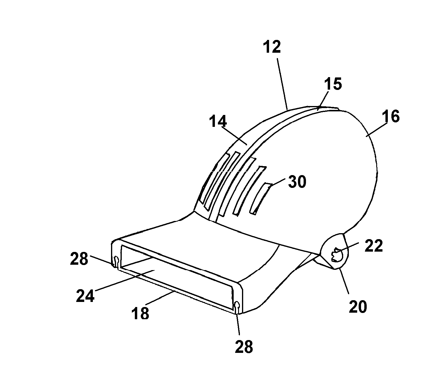
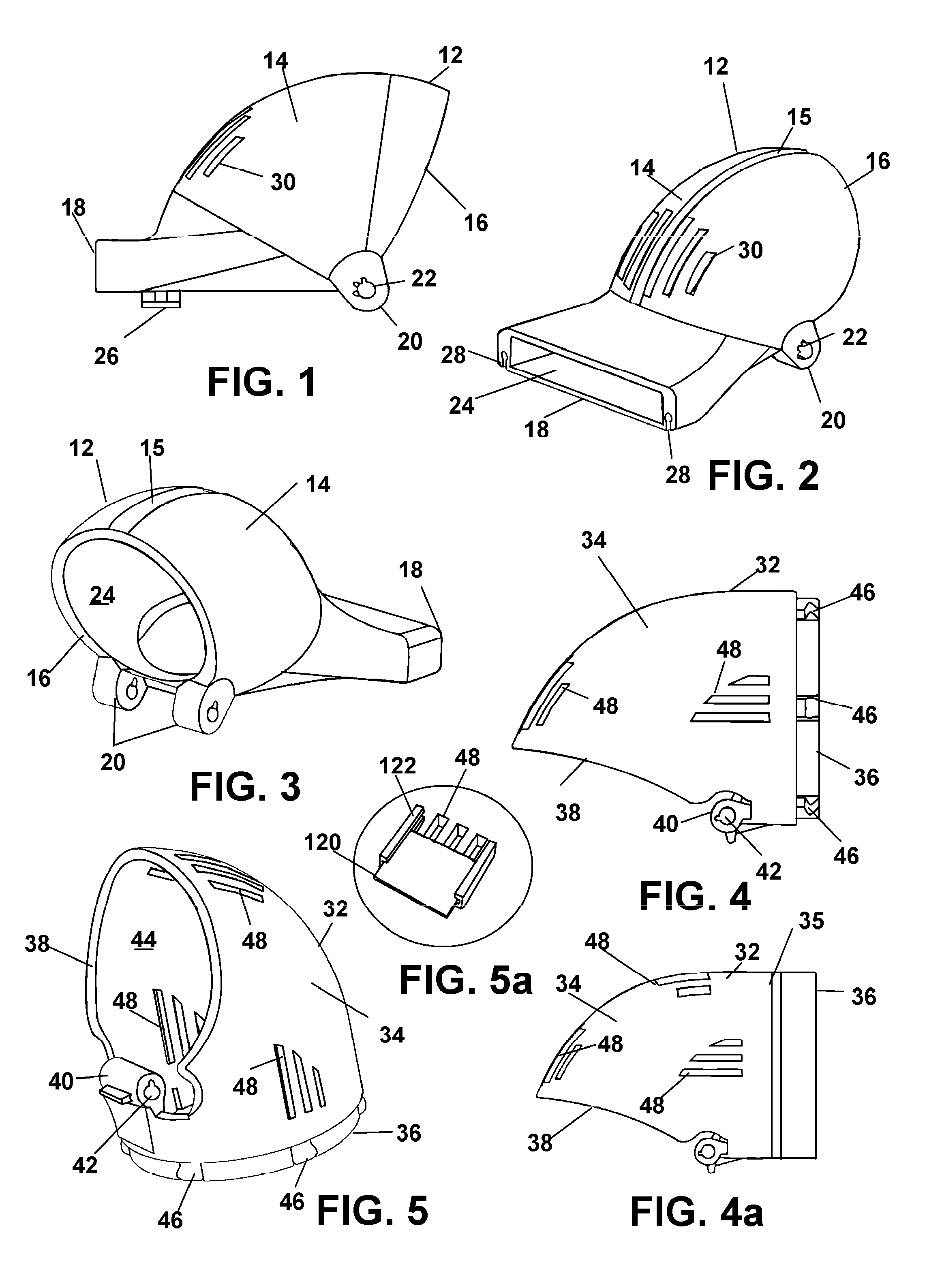
[0083]Now referring to drawings in FIGS. 1-27, wherein similar components are identified by like reference numerals, there is seen in FIG. 1-4a a plurality of body components, each having an interior passage, engageable to each other around a majority of one circumference of each component, and forming an articulating blow dryer airstream vectoring or redirection device 10. The last of two engaged plurality of components in the series, defines the nozzle 12 for exiting air received from the blow dryer operatively engaged to a first of the plurality of body components at the opposite end.

[0084]While the plurality of body components shown in the drawings is two, and two works especially well, the plurality can have more than two components. For instance, a central component (not shown but easily discerned to those skilled in the art) circumferentially engaged on both sides to the first component or nozzle 12 and the second or base component 32. In such a mode of three in the plurality...


PUM


Abstract

A blow dryer attachment for vectoring directional flow of an airstream exiting a barrel of a blow dryer. The attachment features at least two body components in an articulated engagement having a central passage which may be curved by such articulation to reposition and exit aperture in a nozzle end opposite a connection to a blow dryer. A flexible coupling may be provided as an interface to connect the device to a broader range of blow dryers. A rotational engagement of the first component to the blow dryer allows for rotation of the exit aperture around the axis of the blow dryer barrel for additional adjustment of the angle and direction or vector angle of the exiting airstream from the attachment.

Description

[0001]This application is a Continuation in Part application of U.S. patent application Ser. No. 13 / 747,217 filed on Jan. 22, 2013 which claims priority to U.S. Provisional Application Ser. No. 61 / 588,967, filed on Jan. 20, 2012, both of which are incorporated herein in their respective entirety by this reference.BACKGROUND OF THE INVENTION[0002]1. Field of the Invention[0003]The present invention relates generally to hair dryers. More specifically, the device relates to a hair drying component adapted for engagement to a blow dryer, or formed integrally with a hair blow dryer, which has a plurality of positionable and removable nozzle ends intended to improve performance and efficiency in hair styling related tasks for both consumer and professional use through the provision of an air vectoring exhaust end.[0004]A particularly important utility yielded by the device herein is that user comfort and posture is also enhanced by eliminating the unnatural body positions required to empl...

Claims


Application Information

Patent Timeline
IPC IPC(8): A45D20/00
CPCA45D20/00A45D20/124A45D19/16A45D20/122B05B1/12
Inventor TORRES, SERAFINOEDWARDS, SERAFINO
Owner TORRES SERAFINO
Learn More