
Apparatus For Footwear-Embedded Mechanical Energy Harvesting Using Modular Elements

Inactive Publication Date: 2014-02-20
KRUPENKIN THOMAS NIKITA +1
View PDF5 Cites 8 Cited by
  • Summary
  • Abstract
  • Description
  • Claims
  • Application Information

AI Technical Summary

Benefits of technology

The present invention provides a better arrangement for generating energy by combining coils, electrodes, magnets, and droplets. The rigid modules offer improved dimensional stability, allowing for a tighter packing of these components. This results in higher power density. Additionally, a magnetic shield layer may be added to improve the energy conversion efficiency of the structure.

Problems solved by technology

High-power harvesting of mechanical energy from human locomotion is a well known concept which has not been commercialized in the past due to the lack of a viable energy harvesting technology.
Classical methods of mechanical-to-electrical energy conversion (such as electromagnetic, piezoelectric, and / or electrostatic) are not well suited for direct coupling with the forces and displacements typical in human locomotion.
For example, the highly restricted size and form-factor of a footwear-embedded device prevents the use of traditional, mechanical transducers that are necessary to convert a broad range of aperiodic forces and displacements (typically encountered in locomotion) into a readily accessible form.
However, these methods of energy generation are not free from some shortcomings.
This requirement, however, imposes severe restrictions on the dimensional stability of the energy-producing channel, as well as the chain of energy-producing elements.
This means that the relative position and spacing of the electrodes and coils embedded in the channel walls is dynamically changing, potentially creating misalignment between the energy-producing channel elements (electrodes and coils) on one side, and the chain of the energy-producing elements (magnets and microfluidic droplets) on the other side.
This misalignment adversely affects power generation and thus leads to a lower energy harvesting efficiency.

Method used


Image

  • Apparatus For Footwear-Embedded Mechanical Energy Harvesting Using Modular Elements
  • Apparatus For Footwear-Embedded Mechanical Energy Harvesting Using Modular Elements
  • Apparatus For Footwear-Embedded Mechanical Energy Harvesting Using Modular Elements

Examples


Embodiment Construction

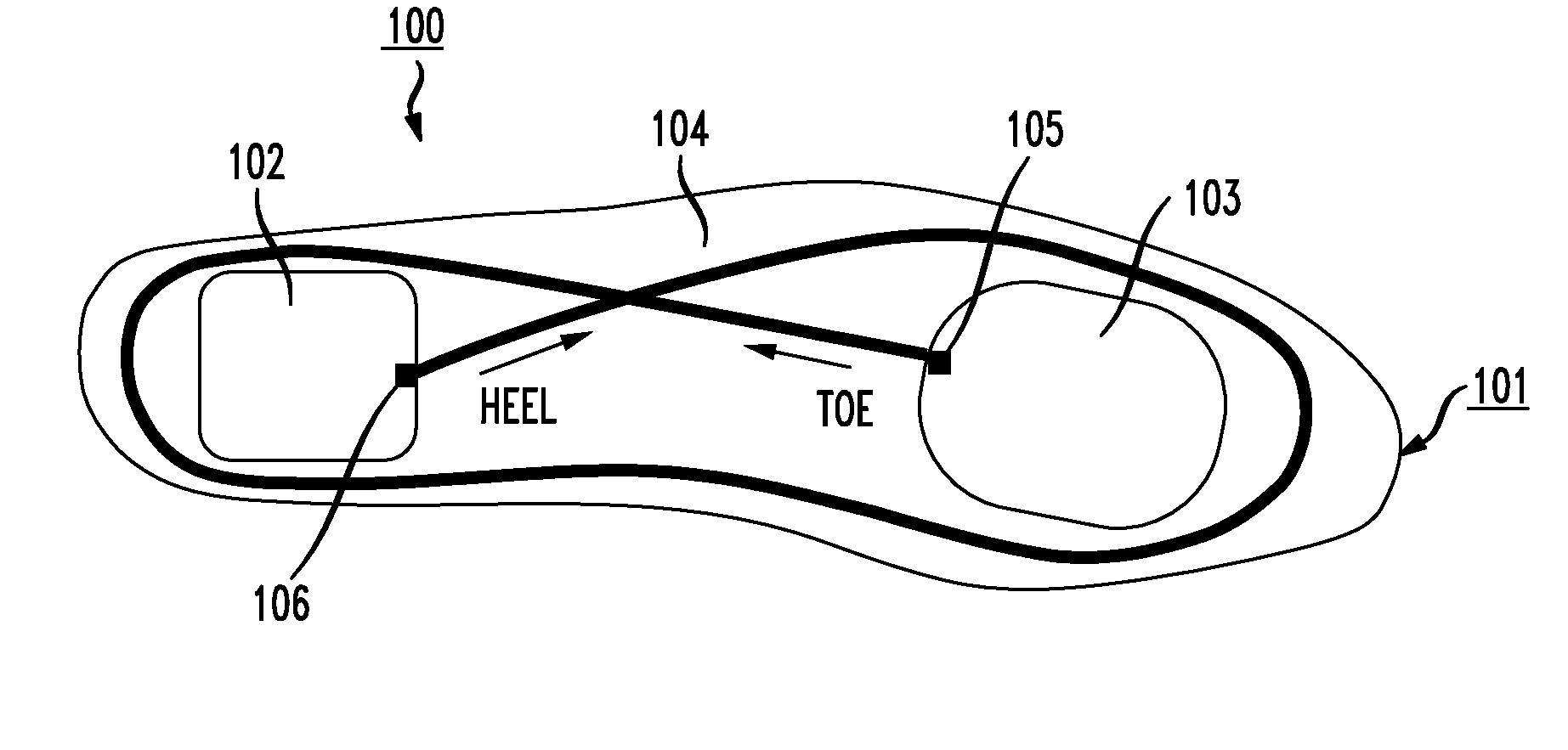
[0041]Prior to explaining the details of the “modular” construction of the energy harvester of the present invention, it is considered useful to review the prior types of energy-producing arrangements that have been developed and described in the above-referenced patents. FIG. 1 presents a two-dimensional schematic view of one exemplary embodiment of an apparatus 100 for capturing mechanical energy from human locomotion and converting it into electrical energy. Apparatus 100 is configured to produce reciprocating motion of an energy-producing chain inside an energy-producing channel as will be discussed in detail below.

[0042]In particular, apparatus 100 comprises an energy-producing channel 104, within which slides an energy-producing chain (not shown). In most arrangements, alternating sets of energy-producing dielectric-coated electrodes and energy-producing conductive coils are formed along the length of energy-producing channel 104. Referring to FIG. 1, apparatus 100 is seen to ...


PUM


Abstract

An energy harvesting apparatus utilizes a modular structure to preserve the proper alignment between a chain of energy-producing elements and an energy-producing channel (within which the chain is located and free to slide along, creating electrical energy from mechanical movement). The channel includes a plurality of rigid modules that are separated by flexible segments of tubing. The rigid channel modules house the energy-producing electrodes and / or coils. The chain includes a plurality of rigid modules that are attached along a flexible string in a spaced-apart configuration. The rigid chain modules house the energy-producing magnets and / or conductive droplets. The combination of the flexible channel segments and chain string allow for freedom of motion of the apparatus (required for human locomotion, for example), while providing the desired “fixed” alignment between the rigid energy-producing modules.

Description

CROSS-REFERENCE TO RELATED APPLICATIONS[0001]This application claims the benefit of U.S. Provisional Application Ser. No. 61 / 684,296 filed Aug. 17, 2012 and U.S. Provisional Application Ser. No. 61 / 700,357 filed Sep. 13, 2012, both of which are herein incorporated by reference.TECHNICAL FIELD[0002]The present invention relates to a mechanical arrangement for harvesting energy from activities such as walking or running and, more particularly, to an arrangement that utilizes a combination of substantially rigid modular elements and flexible elements, the combination maintaining the necessary range of motion required for human locomotion, while providing a certain degree of alignment between the energy-producing components.BACKGROUND OF THE INVENTION[0003]High-power harvesting of mechanical energy from human locomotion is a well known concept which has not been commercialized in the past due to the lack of a viable energy harvesting technology. Classical methods of mechanical-to-electr...

Claims


Application Information

Patent Timeline
IPC IPC(8): F03G5/06H02K7/18
CPCH02K7/1876F03G5/06H02K35/02H02K2213/12H02N1/08
Inventor KRUPENKIN, THOMAS NIKITATAYLOR, JOSEPH ASHLEY
Owner KRUPENKIN THOMAS NIKITA
Features
  • Generate Ideas
  • Intellectual Property
  • Life Sciences
  • Materials
  • Tech Scout
  • Unparalleled Data Quality
  • Higher Quality Content
  • 60% Fewer Hallucinations
Learn More