
Power generation unit driver, power generation unit and energy output equipment in power grid

Inactive Publication Date: 2014-02-20
SIEMENS AG
View PDF19 Cites 16 Cited by
  • Summary
  • Abstract
  • Description
  • Claims
  • Application Information

AI Technical Summary

Benefits of technology

The present invention provides a power generation unit driver, a power generation unit, and an energy storage module for improving the stability of power supply in a power grid using intermittent energy sources. The power generation unit driver receives a first control signal from an electric motor and a second control signal from the power grid, and generates a drive signal accordingly. The energy storage module includes an energy capturing device, a charging controller, an energy storage module, and a power generation unit driver. The power generation unit driver transforms the input energy from the energy capturing device into a second voltage, which is then outputted to the power grid. The power generation unit driver includes a transformer for transforming the second voltage into a third voltage for use by the electric motor. The power generation unit driver also includes an energy storage module that includes an energy storage system and an energy storage managing device for acquiring and utilizing information about the energy storage system as a third control signal. The power generation unit driver can be used in a power grid with intermittent energy sources, improving stability of power supply.

Problems solved by technology

Because the intermittent renewable energy power generation unit has the features of low energy density, high susceptibility to the weather and surrounding conditions, strong fluctuation in output power and low forecasting accuracy, the total installation capacity of intermittent renewable energy power generation units in the microgrid often suffers from a great limitation.
If this limitation is exceeded, safe and stable operation of the microgrid cannot be ensured, and it may adversely cause instability to the external power grid connected thereto.
In that case, the intermittent renewable energy power generation unit does not participate in the regulation of the voltage and frequency in the microgrid, which greatly limits the proportion of its total power generation capacity in the microgrid.
However, because the power levels of the currently available bidirectional converter products are limited and due to technical reasons the number of bidirectional converters operating in parallel connection is also greatly limited, such a microgrid mode suffers from a strong limitation of its system capacity.
Furthermore, in this microgrid mode, since the bidirectional converter achieves system frequency regulation by means of passive regulation of the active power, which causes hysteresis in power control, and the bidirectional converter has limited regulation effects on the reactive power, this microgrid mode cannot fundamentally solve the problem of low connected proportion of the intermittent renewable energy power generation unit in the microgrid.

Method used


Image

  • Power generation unit driver, power generation unit and energy output equipment in power grid
  • Power generation unit driver, power generation unit and energy output equipment in power grid
  • Power generation unit driver, power generation unit and energy output equipment in power grid

Examples


Embodiment Construction

[0103]In order to make the object, technical solution and advantages of the present invention more apparent and clear, the present invention will be further described in detail below with reference to the accompanying drawings and by way of embodiments.

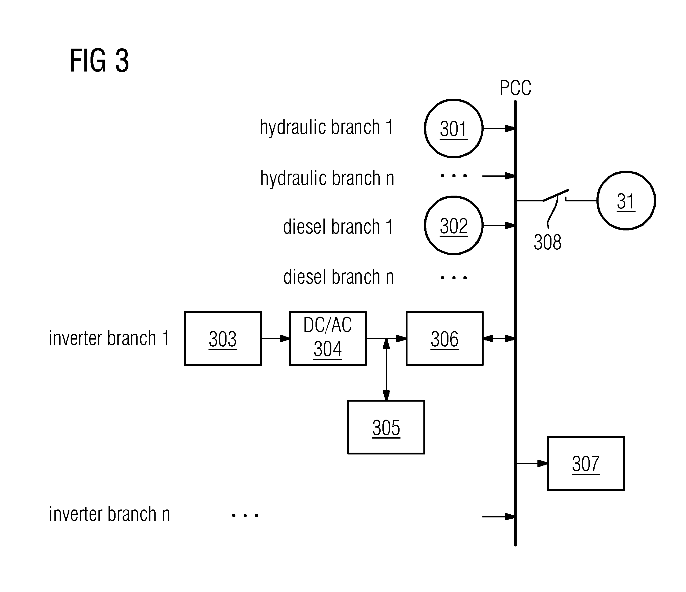
[0104]FIG. 3 shows a microgrid structure different from FIG. 1 or 2, i.e. a third microgrid mode, which includes the following parts: an external power grid 31, and a microgrid. Furthermore, the microgrid includes one or more hydraulic branches, one or more diesel branches, one or more inverter branches, a load 307 and a switch 308. Furthermore, each of the hydraulic branches includes a hydraulic generator 301, each of the diesel branches includes a diesel generator 302, and each of the inverter branches includes a PV array 303, a DC / DC converter 304, a battery 305 and a self-synchronizing inverter 306. In this case, the self-synchronizing inverter 306 can use a solution in which the automatic parallel operation of the voltage source ...


PUM


Abstract

A power generation unit driver, a power generation unit and energy output equipment in a power grid are described. The power generation unit driver includes a drive controller for generating a drive signal according to a first control signal and a second control signal obtained thereby, a converter for transforming the input energy from a first voltage into a second voltage according to the drive signal and outputting the same to an electric motor connected to the power generation unit driver. The first control signal runs condition information of the electric motor, and the second control signal includes the power grid frequency and / or the voltage amplitude of the power grid. The concept produces improved effects on the stability of power supply by a power grid.

Description

TECHNICAL FIELD[0001]The present invention relates to an electrical power system and, particularly, to a power generation unit driver, a power generation unit and energy output equipment in a power grid.BACKGROUND ART[0002]Currently, a microgrid can refer to a small-scale power generation, distribution and utility system composed of one or more portions of a distributed power generation unit, an energy converting device, a monitoring device, a protective device and related loads. In this case, the so-called “small-scale” means that it has a relatively smaller scale compared to the main grid. The microgrid can operate in juxtaposition / in parallel connection / grid-connectedly to an external power grid (such as a main grid, etc.), or can also operate alone. Generally speaking, the microgrid is an autonomous system which can realize self-control, self-protection and self-management.[0003]There are usually various types of power generation units in the microgrid, such as a first energy po...

Claims


Application Information

Patent Timeline
IPC IPC(8): H02P11/06
CPCH02P11/06H02J3/32H02M5/38H02J2300/40H02J2300/10H02J2300/28H02J2300/24H02J3/381Y02E10/56Y02E10/76Y02E70/30
Inventor LI, JINGLIAO, HUALIU, XIN HUAZHANG, JING WEI
Owner SIEMENS AG
Features
  • Generate Ideas
  • Intellectual Property
  • Life Sciences
  • Materials
  • Tech Scout
  • Unparalleled Data Quality
  • Higher Quality Content
  • 60% Fewer Hallucinations
Learn More