
System and method for multi-channel packet transmission

Active Publication Date: 2014-02-20
ALCATEL LUCENT SAS
View PDF10 Cites 6 Cited by
  • Summary
  • Abstract
  • Description
  • Claims
  • Application Information

AI Technical Summary

Benefits of technology

[0009]In radio applications, due to the limited availability of spectrum, it is not desirable to waste radio resources (bandwidth). Therefore, an engineered traffic distribution mechanism is typically required that allows for fully (or at least efficiently) exploiting the available resources. Accordingly an intelligent per flow / conversation protection scheme that is autonomously and dynamically capable of discarding low priority flows / conversations and preserve high priority flows / conversations is desirable.
[0010]Moreover, with the introduction of Adaptive Coded Modulation (in which the modulation, coding and possibly other parameters are typically adapted according to the conditions present on the radio link), it becomes desirable that traffic aggregation and packet protection be performed with a solution capable of overcoming, or at least substantially obviating, the drawbacks of the static approach which is a solution typically provided by some legacy radio systems. Whenever radio bandwidth changes due to radio propagation condition, it is desired that the traffic impact be limited as much as possible, improving the protection efficiency and potentially approaching a ‘hitless’ condition.
[0012]In addition to the above-described scenario, another variable which may need to be kept under control is the latency of the system. Using one channel at a time for the traffic transmission, the delay experienced packet by packet will typically be the one given by the single link. On the contrary, by considering the entire multi-link array as a single Virtual Link, latency may be reduced to improve the performance of the system.
[0020]Standard LAG does not allow to have links with different capacities and to change these capacities dynamically. Additionally, the standard does not allow links having two different capacities in the two directions. This asymmetrical situation may easily occur in presence of adaptive coded modulation.
[0052]According to some specific embodiments, the dispatcher is configured for monitoring the usage of radio resources on each of said plurality of individual transmission channels thereby maintaining knowledge of the load present on a radio link used for such transmission.

Problems solved by technology

In radio applications, due to the limited availability of spectrum, it is not desirable to waste radio resources (bandwidth).
This approach may not guarantee an effective usage of the total bandwidth available and the results may be even poorer if the traffic is encrypted with mechanisms such as IP-SEC (standing for Internet Protocol Security, which relates to providing security to IP traffic using authentication and encryption on IP packets).Standard LAG typically addresses physical layers with high reliability (e.g. fiber or copper).
A change in such status typically happens quite seldom as it can be mainly due to failure (e.g., hardware failure) of the equipment or the line.
On the contrary, when the physical layer is radio with adaptive modulation, the status may correspond to 100% bandwidth availability or less (e.g. 75%, 50%, 25% or 0%) and the change of such status may happen more often as it may be due to radio propagation conditions, e.g. due to weather conditions (which is a normal and expected behavior of radio media).When one of the links becomes unavailable, the total throughput is then typically reduced: standard LAG typically does not guarantee only the dropping of a low priority traffic.
Standard LAG typically does not allow spreading conversations over multiple links at the same time, because reordering is not contemplated.
This leads to a not guaranteed load balance.
When conversations have different bandwidth profiles, allocating each conversation to no more than one channel does not typically allow for fully exploiting the complete multilink available bandwidth.
Typically, the residual bandwidth of each single link will be wasted because no conversation can fit into the remaining available capacity.Standard LAG does not allow to have links with different capacities and to change these capacities dynamically.
Additionally, the standard does not allow links having two different capacities in the two directions.
As a consequence of this negotiation mechanism, it is typically hard to apply a ML-PPP instance over links that change dynamically their own capacity, due to the adaptive coded modulation, and guarantee a hitless traffic distribution.The usage of adaptive coded modulation potentially may lead to asymmetrical link bandwidth due to different propagation conditions over the wireless media (typically the radio bit rate is symmetrical in both direction.
However, as propagation phenomena may be different in forward and backward directions, this may lead to temporary situation in which bit rate becomes asymmetrical)Padding is contemplated.
Consequently, packet protection, namely traffic distribution without significantly disrupting the served traffic, is typically not available using the above technologies.

Method used


Image

  • System and method for multi-channel packet transmission
  • System and method for multi-channel packet transmission
  • System and method for multi-channel packet transmission

Examples


Embodiment Construction

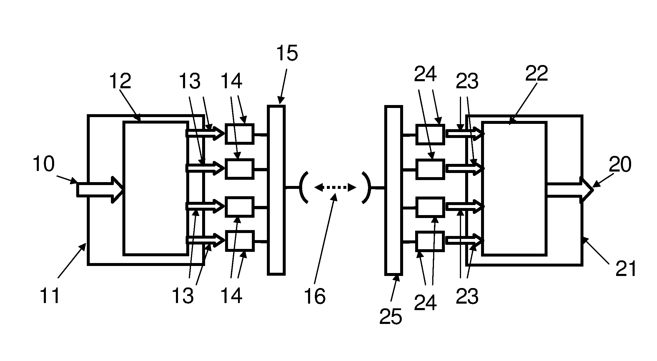
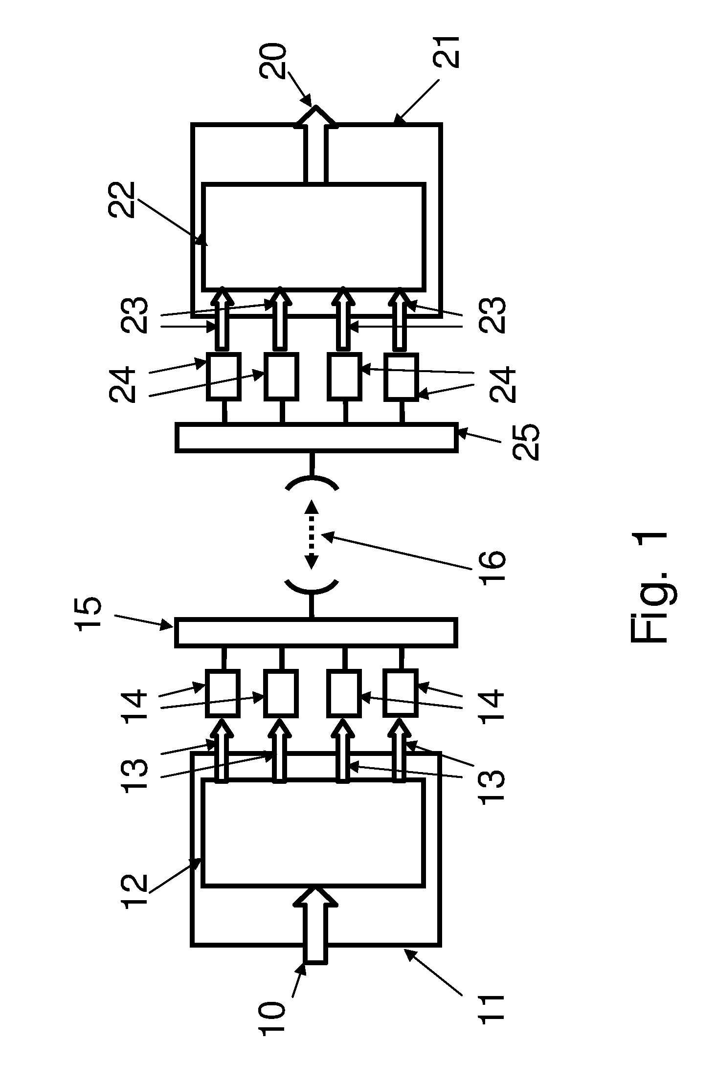
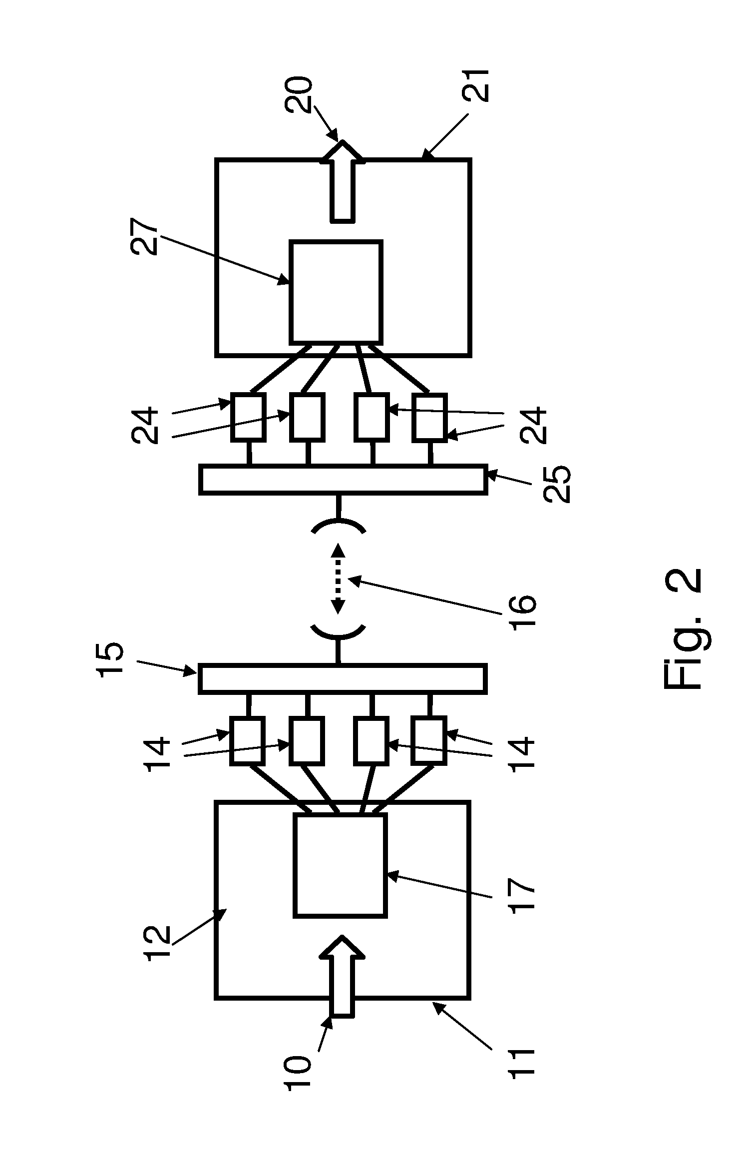
[0066]For a better understanding of the solution proposed herein, a brief description of an exemplary known system is first provided with reference to FIG. 1. In this figure, a conceptual scheme for one possible physical realization of a known point-to-point multi-link radio equipment is represented 1. As shown in the figure an incoming traffic 10 is input into an indoor unit 11 comprising a transmitter module 12 in charge of separating the incoming traffic into a plurality of independent radio channels 13. Each of said independent radio channels 13 is input into a respective microwave transmitter unit 14 which is in charge of transmitting an independent channel through a point-to-point radio connection as generally shown by reference numeral 16 through a branching module 15 which performs an analog sum of the signals to be transmitted.

[0067]At the receive side, the individual channels are received by a branching module 25 which allows for discriminating and filtering the different ...


PUM


Abstract

A method of transmitting packets wherein said packets are comprised in a plurality of flows, the flows comprising flow characteristics controlling admission of incoming flows. A plurality of admitted incoming flows with the same class of service are inserted into a queue. A committed information rate value corresponding to said queue and a bandwidth available for transmission of said queue according to the identified committed information rate value are identified. An order for transmission for the queues is established based on the class of service of the queue and the identified bandwidth. A plurality of cells of the same size are generated from a plurality of frames and the cells are distributed between a plurality of individual transmission channels according to the ordered defined for transmission. A transmitter equipment and a receiver equipment are also disclosed.

Description

[0001]The present invention relates to packet transmission. In a variant, the invention relates to packet radio transmission.BACKGROUND ART[0002]Some wireless communication systems are based on packet radio paradigm. An example of such systems is the so-called Ethernet radio systems. Such packet radio systems typically require transmission schemes with the following functionalities:[0003]exploit as fully as possible the available bandwidth of point-to-point multi-link radio equipments;[0004]guarantee as much as possible a high level of quality of service (QoS), traffic aggregation and drop precedence;[0005]dynamic admission control of packets or frames;[0006]fast restoration of traffic in case of hardware failure;[0007]no, or insignificant impact on traffic in case of single or multiple radio failure or multi-link throughput change.SUMMARY[0008]In view of the above requirement, a new approach is desired in designing the architecture of new generation point-to-point multi-link wirele...

Claims


Application Information

Patent Timeline
IPC IPC(8): H04W28/02H04L47/52
CPCH04W28/0268H04L47/2441H04L47/34H04L47/522H04L47/6215H04W28/065H04W72/1263H04W28/0252H04W72/52H04W28/082H04L49/90H04W28/10H04L49/9057H04L47/628H04L47/125H04W8/04
Inventor PASOTTI, MARCODI PRISCO, PAOLOCORBETTA, GIULIANOBARZAGHI, GIORGIOVODOLA, FRANCESCODE BLASIO, GIUSEPPEGEROSA, MARZIOSALGARELLI, LUCAGRINGOLI, FRANCESCO
Owner ALCATEL LUCENT SAS
Learn More