Method And Arrangement For The Optical Evaluation Of Harvested Crop In A Harvesting Machine

Active Publication Date: 2014-02-20
DEERE & CO
View PDF1 Cites 39 Cited by
  • Summary
  • Abstract
  • Description
  • Claims
  • Application Information

AI Technical Summary

Benefits of technology

[0006]According to the present invention, there is provided an improved method

Problems solved by technology

Thus, for example, he can enlarge the threshing gap and reduce the speed of the threshing drum if the proportion of broken grain is too high.
In this conn

Method used


Image

  • Method And Arrangement For The Optical Evaluation Of Harvested Crop In A Harvesting Machine
  • Method And Arrangement For The Optical Evaluation Of Harvested Crop In A Harvesting Machine
  • Method And Arrangement For The Optical Evaluation Of Harvested Crop In A Harvesting Machine

Examples


Embodiment Construction

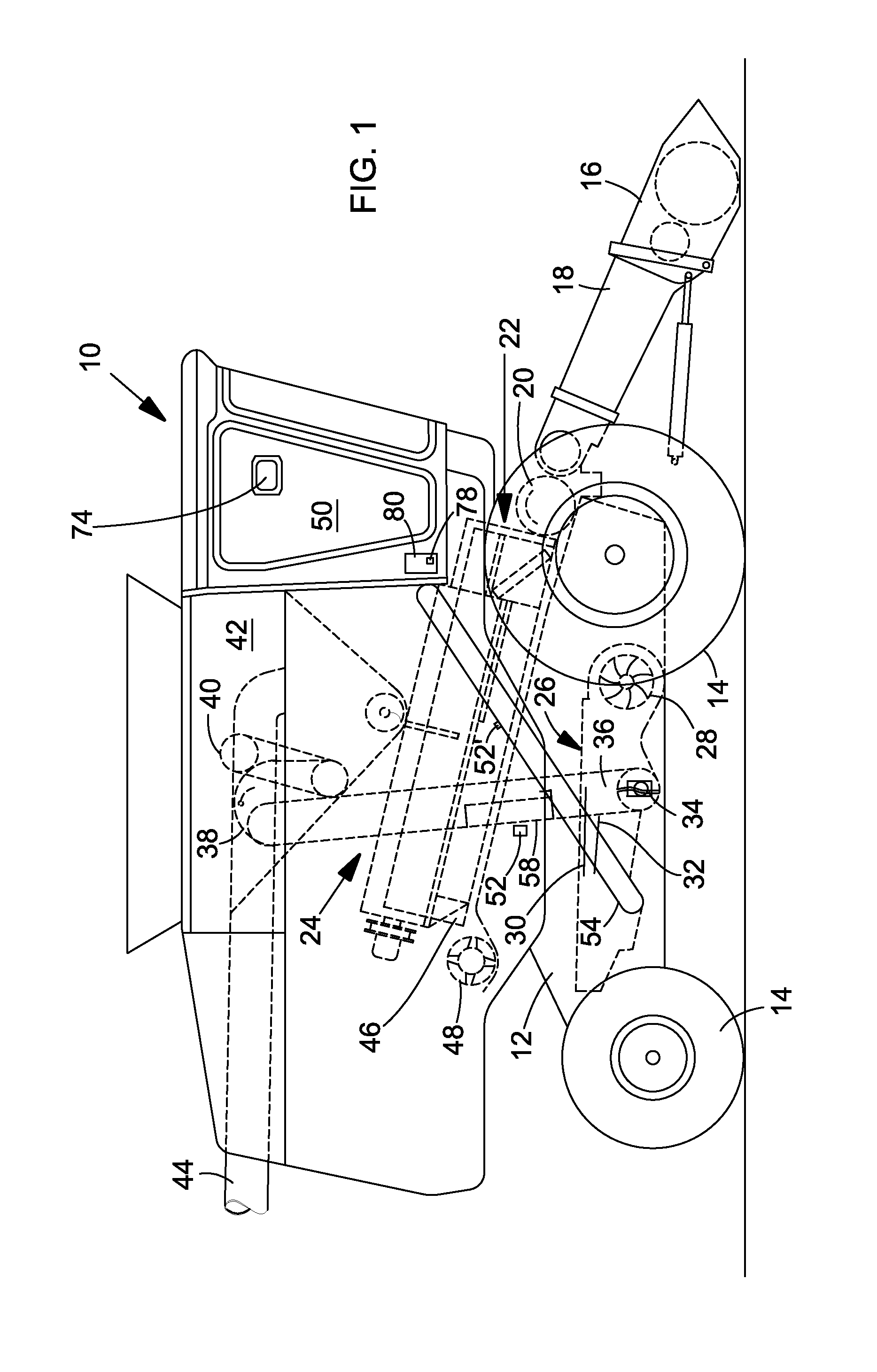
[0023]Reference is now made to FIG. 1 which shows an agricultural harvesting machine in the form of a combine-harvester 10, which includes a main frame 12 with driven front and steerable rear wheels 14 in contact with the ground, which wheels support the main frame 12 for forward movement over a field to be harvested. Although wheels 14 are shown, the combine-harvester 10 can be supported completely or in part by caterpillar running gear which is in contact with the ground. The drive of the front wheels 14 is effected by means of a conventional hydrostatic transmission from a combustion engine fastened on the main frame. Directional specifications (such as forward) below relate to the forward direction of the combine-harvester 10, which moves to the right in FIG. 1.

[0024]A vertically adjustable harvest attachment in the form of cutting gear 16 is used in order to harvest crop and supply it to a slope conveyor 18. The slope conveyor 18 is pivotably mounted on the main frame 12 and in...


PUM


Abstract

An arrangement for the optical evaluation of harvested crop in a harvesting machine includes a camera located for taking images of threshed out crop elements (grain and material other than grain) being conveyed within a channel of the machine. An electronic image processing system receives the images and identifies individual objects in the images, these objects being classified into predetermined object classes by way of comparing at least one of color, contour or texture features of the individual objects and corresponding characteristics of reference objects filed in a data bank. The processing system then determines the absolute or relative numbers or areas of the individual objects assigned to the respective object classes.

Description

FIELD OF THE INVENTION[0001]The present invention relates to a method for the optical evaluation of harvested crop.BACKGROUND OF THE INVENTION[0002]Combine-harvesters are large machines which harvest grain from a field, thresh it and clean it. A combine-harvester includes a number of adjustable elements, such as the size of the openings of a threshing basket or of a separating screen, the size of a threshing gap, the speed of a threshing drum, the speed of a cleaning blower or the position of slats of a sieve. The optimum operating parameter of said elements depends on the type of harvested crop and the characteristics thereof and can change over time. The adjustment of said parameters is usually carried out by the operator of the combine-harvester on the basis of operating instructions or his experience or it is carried out automatically using values which are filed in a memory and which are called up by the operator as a function of the current conditions of the surrounding area a...

Claims


Application Information

Patent Timeline
IPC IPC(8): A01D41/127G06V10/56G06V20/66G06V20/68
CPCA01D41/1277G01J3/50G01N21/85G01N2021/8592G01B11/02G06T7/0004G06T2207/30128G06T2207/30188G06T2207/30242G06T7/11G06T7/194G06V10/56G06V20/66G06V20/68G06F18/00G01N21/00
Inventor BRUECKNER, PETERLERM, STEFFENGARTEN, DANIELHOLDER, SILVIO
Owner DEERE & CO
Why Eureka
Try Eureka