Replaceable roller bearing

a roller bearing and roller bearing technology, applied in bearing repair/replacement, bearing rigid support, manufacturing tools, etc., can solve the problems of wheel and rail bearing assembly, affecting the service life of the bearing, and being exposed to harsh elements. , to achieve the effect of increasing separation

Active Publication Date: 2014-02-20
SOFEC
View PDF4 Cites 33 Cited by
  • Summary
  • Abstract
  • Description
  • Claims
  • Application Information

AI Technical Summary

Benefits of technology

[0017]A removable axial spacer secures the vessel and the turret into engagement with the upper and lower thrust bearing assemblies. Removal of the spacer allows increased separation between the vessel and turret flanges that sandwich the thrust bearings. The mid radial bearing assembly includes one or more radially arranged bearing

Problems solved by technology

Wheel and rail bearing assemblies, such as shown in FIG. 2 or in the Commandeur patent, are bulky and somewhat restricted in their load capacity.
In addition, wheel and rail bearings are typically not sealed but are instead exposed to the harsh elements of the sea environment.
This characteristic means that these bearings are subject to corrosion and failure and therefore require regular maintenance.
The integrated three-row rolle

Method used


Image

  • Replaceable roller bearing
  • Replaceable roller bearing
  • Replaceable roller bearing

Examples


first embodiment

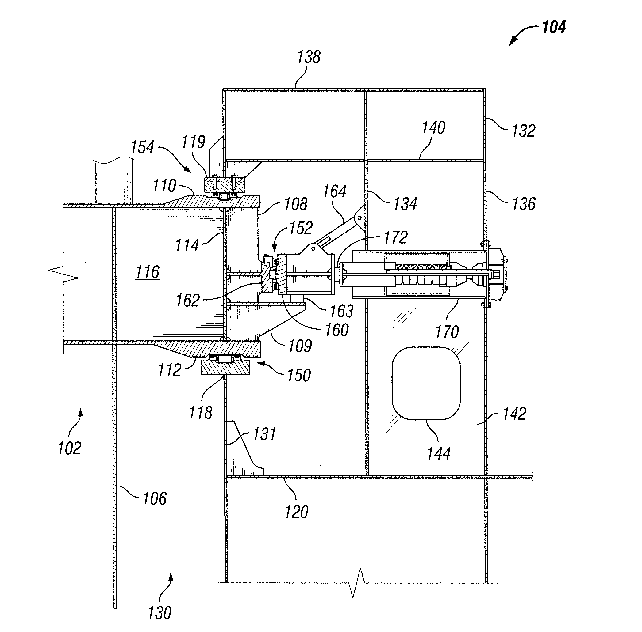
[0040]In a first embodiment, turret 102 is rotatively coupled within moon pool 130 by an arrangement of three discrete roller bearing assemblies, including a lower main support thrust roller bearing 150, a mid radial roller bearing 152, and an upper retaining thrust roller bearing 154. Each of the roller bearings 150, 152, 154 is preferably individually lubricated and sealed. The upper and lower thrust bearings 154, 150 maintain turret 102 in axial alignment within moon pool 130. The radial bearing 152 maintains the relative radial position of turret 102 within moon pool 130. Unlike an integrated three-row roller bearing assembly of prior art, the roller bearings 150, 152, 154 of the present invention are preferably capable of being individually segmented, and at least the main thrust bearing 150 is preferably arranged and designed to be replaced in situ, as described below with respect to FIGS. 13 and 14.

[0041]A lower circular flange 118 having a tee-shaped cross-sectional profile ...

second embodiment

[0047]FIG. 5 discloses a vessel-turret bearing arrangement according to the invention. Turret 202 and vessel 204 of FIG. 5 are substantially similar to turret 102 and vessel 104 of FIG. 4, except that outer ring 160 of the mid radial roller bearing is carried by vessel 204 rather than turret 202. A series of shelves 209 (only one shelf 209 is visible in FIG. 5) mounted to the interior wall of concentric ring 134, such as by welding, vertically support outer ring 160. A plain bearing pad 163 disposed between outer ring 160 and shelf 209 slidingly supports outer ring 160 as vessel 204 shifts slightly into and out of coaxial alignment with turret 202 under the combined forces of wind, waves and current and the restoring force due to spring packs 170. An alternative embodiment of torque control arm assembly 264 is adapted to allow small amounts of radial and vertical movement between turret support structure 132 and outer ring 160 while arresting circumferential torque on outer ring 160...

third embodiment

[0049]FIG. 6 discloses a vessel-turret bearing arrangement according to the invention. Like the arrangement of FIGS. 4 and 5, turret 302 and vessel 304 are rotatively coupled using a discrete lower main thrust roller bearing 150 and a discrete upper retaining thrust roller bearing 154. However, the mid radial bearing 352 is a plain bearing rather than a roller bearing. An inner circular bearing surface 362 is secured to arm 108 of turret 302, and an outer bearing surface 360 is secured to the radial series of spring packs 170. At each spring pack 170, a bearing pad 372, made of Orkot® for example, is disposed between inner and outer bearing surfaces 362, 360.

[0050]The embodiments of FIGS. 4 and 5 each in effect have two mid coaxially located radial bearings—roller bearing 152 and plain bearing pads 172. The embodiment of FIG. 6 is substantially simplified in comparison, with only plain bearing pads 372. The heavy outer ring 160 and supporting shelves 109, 209, and torque control arm...


PUM

PropertyMeasurementUnit
Weightaaaaaaaaaa
Lengthaaaaaaaaaa
Diameteraaaaaaaaaa

Abstract

A turret/vessel bearing arrangement and method for replacing bearings in situ without removing other bearings. The bearings are capable of being separated. A removable axial spacer secures the vessel and the turret into engagement with the upper and lower thrust bearings. Removal of the spacer allows increased separation between vessel and turret flanges that sandwich the thrust bearings. The mid radial bearing assembly includes one or more radially arranged bearing pads that allow for limited axial displacement of the turret with respect to the vessel during thrust bearing replacement while still bearing radial loads and allowing rotation. The addition of a temporary thrust bearing allows the vessel to weathervane about the turret while thrust bearing are replaced in situ.

Description

BACKGROUND OF THE INVENTION[0001]1. Field of the Invention[0002]This invention relates to a turret structure for vessels such as offshore drilling or production vessels, and more particularly to a turret bearing arrangement that can be replaced in situ.[0003]2. Background Art[0004]Vessel mooring systems are known in the art in which a vessel may weathervane about a turret that is moored to the sea floor. The turret extends through a moon pool or cylindrical opening that extends through the hull of the vessel. The vessel is supported for rotation with respect to the turret by bearing structures placed between the turret and the vessel. Horizontal and vertical bearings transfer horizontal and vertical loads between the turret and the vessel.[0005]FIG. 1 discloses such a turret mooring system, which is more fully described in co-pending U.S. patent application Ser. No. 13 / 446,857 filed on Apr. 13, 2012 in the names of Lindblade et al., which is incorporated herein by reference. FIG. 1 ...

Claims


Application Information

Patent Timeline
IPC IPC(8): F16C21/00B23P6/00F16C19/38F16C19/30F16C19/54
CPCF16C21/00F16C35/062F16C19/545F16C2237/00F16C19/26F16C19/30F16C2326/00F16C2300/14F16C2326/30Y10T29/4973B63B21/507F16C35/061
Inventor LINDBLADE, STEPHEN P.FONTENOT, WILLIAM LOUISPRATT, JAMES NELSON
Owner SOFEC
Why Eureka
Try Eureka