Flow cytometer disinfection module

a flow cytometer and module technology, applied in the direction of material analysis by transmitting radiation, instruments, measurement devices, etc., can solve the problems of reducing yield, affecting the efficiency of filtration and centrifugation, and slow cell separation rate, so as to save time, damage possible microorganisms in the fluid, and be easily attached to the existing cytometer

Active Publication Date: 2014-02-20
DEUT RHEUMA FORSCHUNGSZENT BERLIN +1
View PDF4 Cites 24 Cited by
  • Summary
  • Abstract
  • Description
  • Claims
  • Application Information

AI Technical Summary

Benefits of technology

[0019]The various aspects of the present invention, such as the device, method and use of the device described herein, represent a unified invention, as all are defined by novel and inventive features in light of the cited prior art. It was at the date of filing unknown, that preferably UV-C and / or UV-B light can be used for disinfection in a flow cytometer, especially without the need to replace the cytometer. The novel and inventive module can easily be attached to existing cytometer.
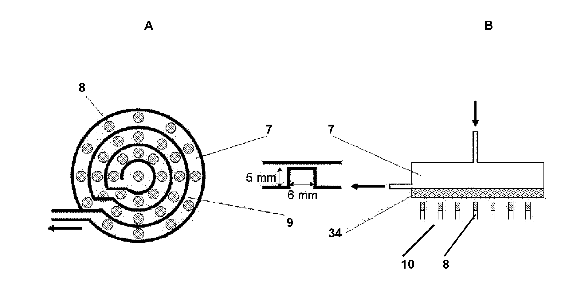
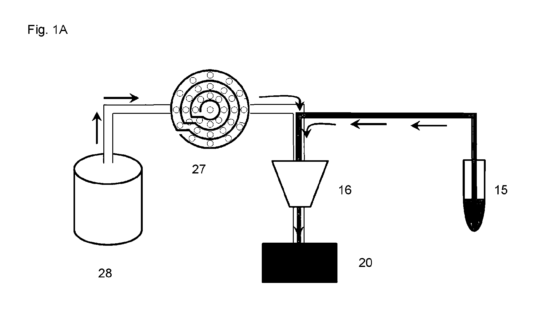
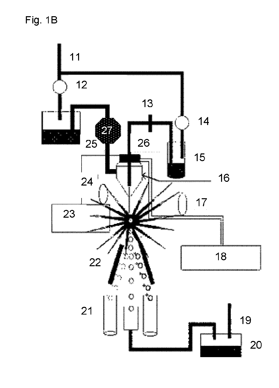
[0020]In a first aspect, the invention concerns a flow cytometer disinfection module, comprising a flow cell and at least one preferably UV-C and / or UV-B light source, wherein the at least one preferably UV-C and / or UV-B light source is disposed about the cell and irradiates a sheath fluid passing through the cell. It was very surprising, that a preferably UV-C and / or UV-B light source, especially a UV-C semiconductor or a UV-C LED can be used to disinfect the sheath fluid in a cytometer, wherein at least one light source is disposed about the cell through which the sheath fluid is flowing. The preferably UV-C and / or UV-B light is irradiating the sheath fluid, thereby damaging possible microorganisms in the fluid irreparably. This embodiment not only realises saving of time, but also of material, work steps and costs. The use of an UV light source based disinfection module in flow cytometer, especially in cell sorting machines results in a significant reduction in preparation time before the sorting or analysis of the cells because a flushing of the tubing of the cytometer is not necessary anymore. In addition, the incorporation of the module in a flow cytometer is an additional safety step to ensure the work with not contaminated carrier liquids. The quality of the sorting or the analysis of the cells increases significantly.

Problems solved by technology

However, when the cell population of interest does not differ significantly in size or density, the filtration and centrifugation techniques are ineffectual.
Furthermore, the rate of cell separation is relatively slow due to the fact that FACS sorters operate by examining a single cell at a time.
Higher cell sorting rates are possible, however, these higher sorting rates may decrease the yield.
Still further, FACS sorters are relatively expensive and thus, most laboratory facilities are equipped with a limited number of sorters.
Firstly, the cell sub-population of interest can be physically damaged during the HGMS process because of their forced magnetic massing at the collector device.
Despite these advances, many failures of these instruments are due to problems in the flow chamber or the nozzle.
For example, orifice clogging, particle adsorption and contamination in the tubing may cause turbulent flow in the jet stream.
These problems contribute to the great variation in illumination and detection in conventional FACS devices.
Another major problem is known as sample carryover, which occurs when remnants of previous specimens left in the channel back-flush into the new sample stream during consecutive runs.
Although such systems can be sterilized between runs, it is costly, time consuming, inefficient, and results in hours of machine down time for bleaching and sterilization procedures.
Sterile cell sorting is one of the biggest challenges in flow cytometry.
Usually cell sorter are not in a sterile environment and therefore the risk of contaminations exists.
However, these reagents are expensive and some are toxic for cells if they are not completely washed.
UV-B is typically the most destructive form of UV radiation because it has enough energy to cause photochemical damage to cellular DNA, yet not enough to be completely absorbed by the atmosphere.
Ultraviolet light kills microorganisms by damaging the DNA.
UV radiation disrupts the chemical bonds that hold the atoms of DNA together in the microorganism.
If the damage is severe enough, the bacteria cannot repair the damage and will die.
Unlike chemical treatments, UV-treated air or water does not resist re-contamination.
Microorganisms floating in the air or on an outer surface may easily be reached by the ultraviolet rays and, therefore, are readily destroyed.

Method used


Image

  • Flow cytometer disinfection module
  • Flow cytometer disinfection module
  • Flow cytometer disinfection module

Examples


example 1

UV-C and / or UV-B Disinfection-Module Integration in a BD FACS Diva Cell-Sorter

1. Detection of any Existing Contamination in the Cell Sorter

[0070]sample taking (Phosphate Buffered Saline—PBS) from sheath container and PBS stream below the nozzle (each 100 μl)[0071]receiving the samples in Lysogeny Broth Medium (culture medium for bacteria)[0072]incubation at 37° C. in a rotating shaker[0073]after 24 h a clearly contamination was visible in both samples

2. Endotoxin Test at Different Irradiation Dose

[0074]Endotoxin is a component of the outer cell membrane of gram-negative bacteria. It can be detected by a photometric LAL-test.

light power (mW / lightsamplesource)Endotoxin Units (EU / ml)PBS container0 (positiv control)1.01PBS flow stream*0>4.95PBS flow stream*0.22.08PBS flow stream*0.41.79PBS flow stream*0.61.55PBS flow stream*0.81.31PBS flow stream*12.08 (measurement error)PBS flow stream*0 (control)1.25PBS autoclaved0 (control)3.47*PBS taken below the nozzle

Results (See e.g. FIG. 7):[007...


PUM

PropertyMeasurementUnit
UV reflectanceaaaaaaaaaa
flow ratesaaaaaaaaaa

Abstract

A flow cytometer disinfection module is useful for disinfecting a sheath fluid in a flow cytometer. The module includes a flow cell and at least one UV-C and/or UV-B light source. The UV-C and/or UV-B light source is disposed about the cell and irradiates a sheath fluid passing through the cell

Description

[0001]The invention concerns a flow cytometer disinfection module for disinfecting a sheath fluid in a flow cytometer, comprising a flow cell and at least one preferably UV-C and / or UV-B light source. The preferably UV-C and / or UV-B light sources are disposed about the flow cell and irradiate the sheath fluid flowing through the cell. The invention also concerns a method for disinfecting a sheath fluid in a flow cytometer.BACKGROUND[0002]Generally, cell sorting devices separate cell populations of interest from a suspension and / or other types of cells. The principal method of Operation of early cell sorting devices relied on a cell's physical parameters to distinguish that cell from a suspension and / or other types of cells. Examples of bulk cell sorting techniques include filtration, which is based on cell size, and centrifugation, which is based on cell density. These techniques are effective as long as the cell population of interest is significantly different, with respect to siz...

Claims


Application Information

Patent Timeline
Patent Type & Authority Applications(United States)
IPC IPC(8): A61L2/10
CPCA61L2/10G01N15/1404G01N2015/1409G01N2015/149
Inventor KNEISSL, MICHAELKAISER, TORALFKOLBE, TIM
Owner DEUT RHEUMA FORSCHUNGSZENT BERLIN
Why Eureka
Try Eureka