Method for Globally Optimizing Power Flows in Electric Networks

a technology of power flow and global optimization, applied in non-electric variable control, process and machine control, instruments, etc., can solve the problems of relaxed convex optimization, inability to guarantee global optimal voltage and generator level for efficient operation, and inability to achieve feasible solutions with a global minimum. the effect of convergen

Active Publication Date: 2014-02-20
MITSUBISHI ELECTRIC RES LAB INC
View PDF4 Cites 26 Cited by
  • Summary
  • Abstract
  • Description
  • Claims
  • Application Information

AI Technical Summary

Benefits of technology

[0012]A spatial branch and bound (BB) procedure ensures that the globally optimal solution is attained. The BB procedure partitions the feasible region of the power flow problem, specifically by partitioning the bound on generation variables and also constraints on voltage magnitudes, which speeds up convergence.

Problems solved by technology

However, such assumptions may not be valid for all networks.2) Use nonlinear programming (NLP) to determine a lowest cost per kilowatt hour delivered.
However, NLP cannot guarantee the globally optimal voltages and generator levels for efficient operation.3) Use a relaxation of OPF to convex optimization, such as second-order cone programming (SOCP).
However, such relaxed convex optimizations do not guarantee feasible solutions with a global minimum for the original problem.4) Use a relaxation of OPF to semi-definite programming (SDP), which requires changing resistances of lossless lines in the network, restrictions on the network topology or constraints, or require modification of the network to ensure global optimality.5) Use a branch & bound (BB) procedure with Lagrangian duality (LD) based lower bounds that do not consider all necessary constraints and are considerably slow due to the irregular nature of the optimization problem.

Method used


Image

  • Method for Globally Optimizing Power Flows in Electric Networks
  • Method for Globally Optimizing Power Flows in Electric Networks
  • Method for Globally Optimizing Power Flows in Electric Networks

Examples


Embodiment Construction

[0022]Electrical Power Network Topology

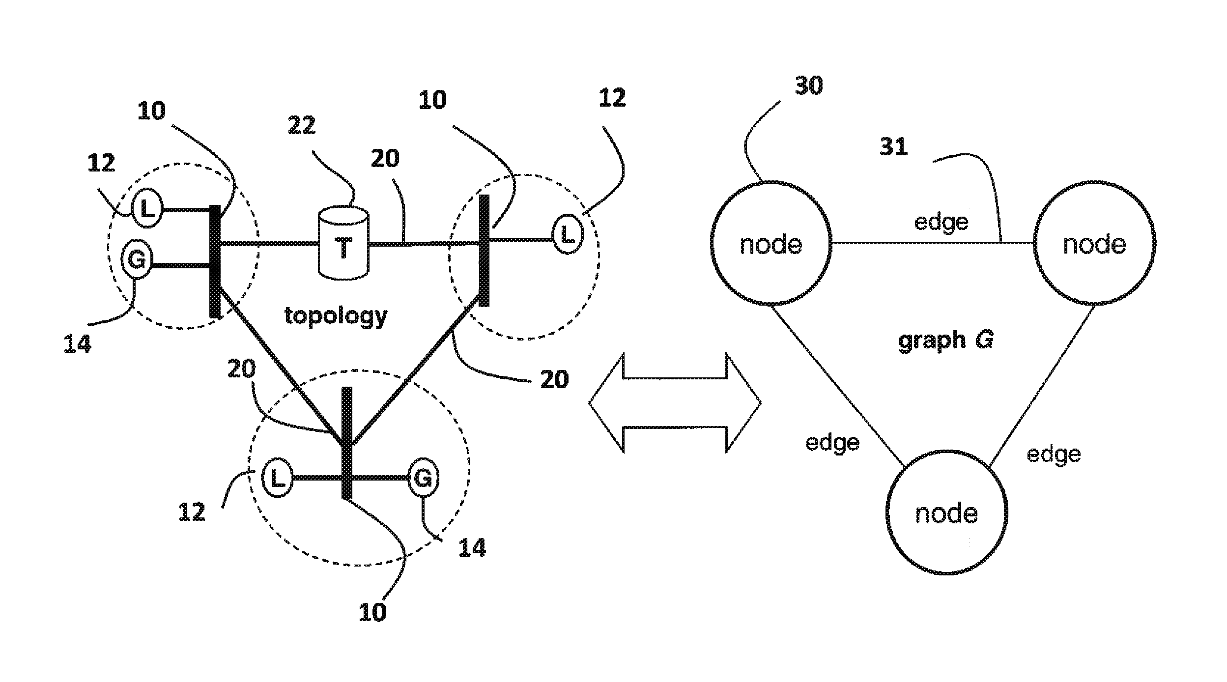
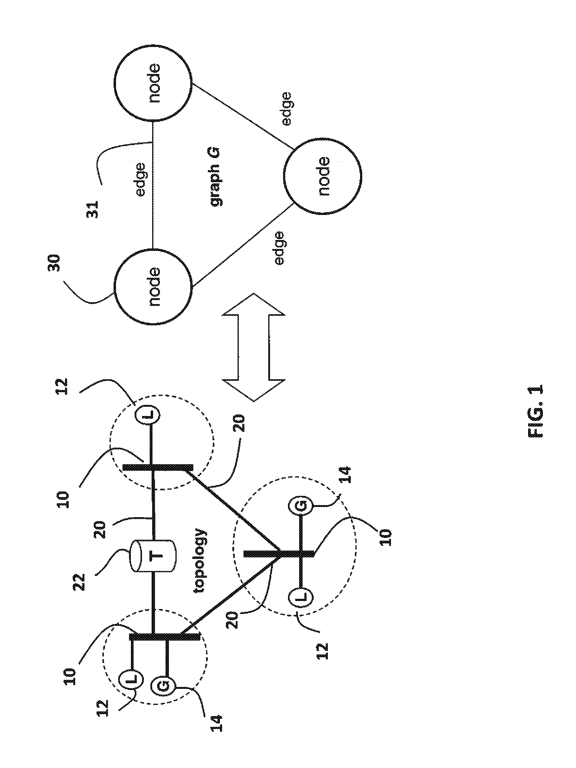
[0023]FIG. 1 shows an electric power network topology that can use embodiments of our invention. The network can include AC and DC components connected by convertors. The only requirement is that variables and constraints that control the operation of the network are continuously controllable.

[0024]The network includes buses 10 connected to loads 12 and generators 14. The buses are interconnected by transmission lines 20, also known as branches. Some of the transmission lines can be connected to transformers 22.

[0025]The generators generate active power (measured in MW), and reactive power (measured in MVar). The loads consume the power. The power is defined by voltage magnitude and phase angle.

[0026]The parameters for the optimization include, but are not limited to, an admittance matrix based on the branch impedance and bus fixed shunt admittance, and the flow capacity ratings, i.e., the maximal total power flow constrained by thermal ratings...


PUM


Abstract

A power flow problem (OPF) in an electric power network is globally optimized using a branch and bound tree of nodes connected by edges. The BB initially includes at least a root node, and each node represents a feasible region of limits on voltages and powers. An upper bound on the OPF problem is solved for selected nodes using nonlinear programming, while a lower bound is solved using a convex relaxation. The lowest upper and lower bounds are updated using the current upper and lower bound. If a difference between the lowest upper and lowest lower bound is less than a threshold, then outputting the voltages and the powers for the electric power network as represented by the feasibility region for the selected node. Otherwise, the feasible region of the node is partitioned to replace the node. The process is repeated until the tree is empty.

Description

FIELD OF THE INVENTION[0001]The present invention relates generally to electric power networks, and more particularly to optimizing power flows in the networks.BACKGROUND OF THE INVENTION[0002]An electric power network includes buses connected to transmission lines. The buses are connected to generators and loads. Optimal power flow (OPF) analysis is often used for monitoring and controlling the operation of the network. The power flow depends, in part, on voltage magnitudes and phase angles. Generation amounts and voltage levels on the buses are optimized by minimizing an objective function subject to constraints, such as the magnitudes, phases, power transferred, generator capacity, thermal losses, and the like.[0003]Most conventional OFF optimizations:[0004]1) Use simplifying assumptions, such as small differences between phase angles at buses, to reduce quadratic equalities and inequalities to linear equalities and inequalities. However, such assumptions may not be valid for all...

Claims


Application Information

Patent Timeline
Patent Type & Authority Applications(United States)
IPC IPC(8): G06F1/26
CPCH02J3/00H02J2203/20Y02E40/70Y02E60/00Y04S10/50Y04S40/20
Inventor RAGHUNATHAN, ARVINDGOPALAKRISHNAN, AJITNIKOVSKI, DANIEL NIKOLAEV
Owner MITSUBISHI ELECTRIC RES LAB INC
Why Eureka
Try Eureka