Full expansion internal combustion engine with co-annular pistons

a technology of internal combustion engine and co-annular piston, which is applied in the direction of engine sealing arrangement, cylinder, feed system, etc., can solve the problems of limiting the thermal efficiency that can be achieved with these engines, reducing efficiency, and reducing release, so as to achieve high-energy ignition source, significant power output, and large heat energy reduction

Inactive Publication Date: 2014-02-27
TAYLOR PATENT HLDG CO LLC
View PDF6 Cites 0 Cited by
  • Summary
  • Abstract
  • Description
  • Claims
  • Application Information

AI Technical Summary

Benefits of technology

[0008]The co-annular dual piston cylinder can be operated at conventional compression ratios with a significant power output, particularly when operated with high velocity inlet air swirl flow, a stratified charge fuel injector spray, and a high energy ignition source. The operation of the co-annular dual piston cylinder delivers large reductions in the heat energy that is normally lost to the cooling system, and in the energy normally lost in the engine exhaust system.

Problems solved by technology

Conventional IC engines are limited in compression ratio by the requirement that the fuel must be burned at stoicheometric premixed fuel-air ratios with no detonation or pre-ignition, which limits the thermal efficiency that can be achieved with these engines.
However, diesel engines use compression ignition of fuel that is not well mixed, resulting in a significant combustion delay time and reduced release of energy at the beginning of the power stroke, which results in reduced efficiency.

Method used


Image

  • Full expansion internal combustion engine with co-annular pistons
  • Full expansion internal combustion engine with co-annular pistons
  • Full expansion internal combustion engine with co-annular pistons

Examples


first embodiment

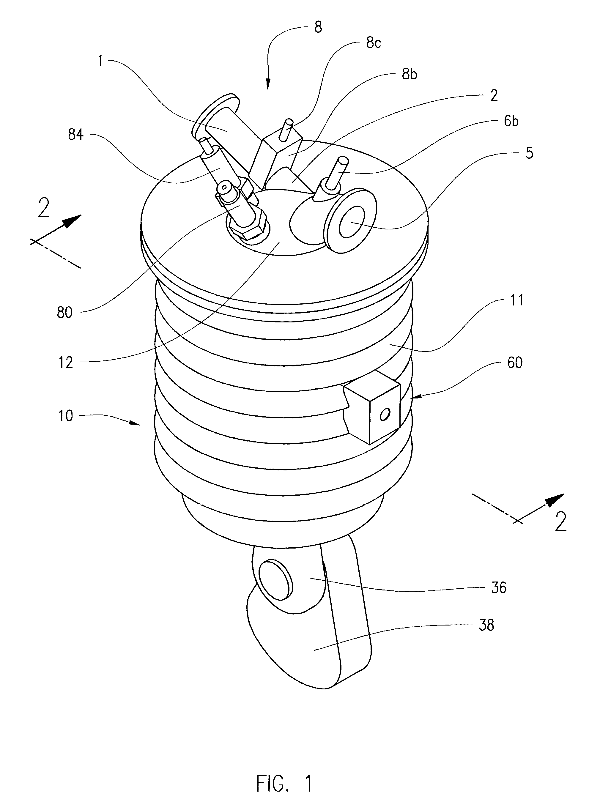
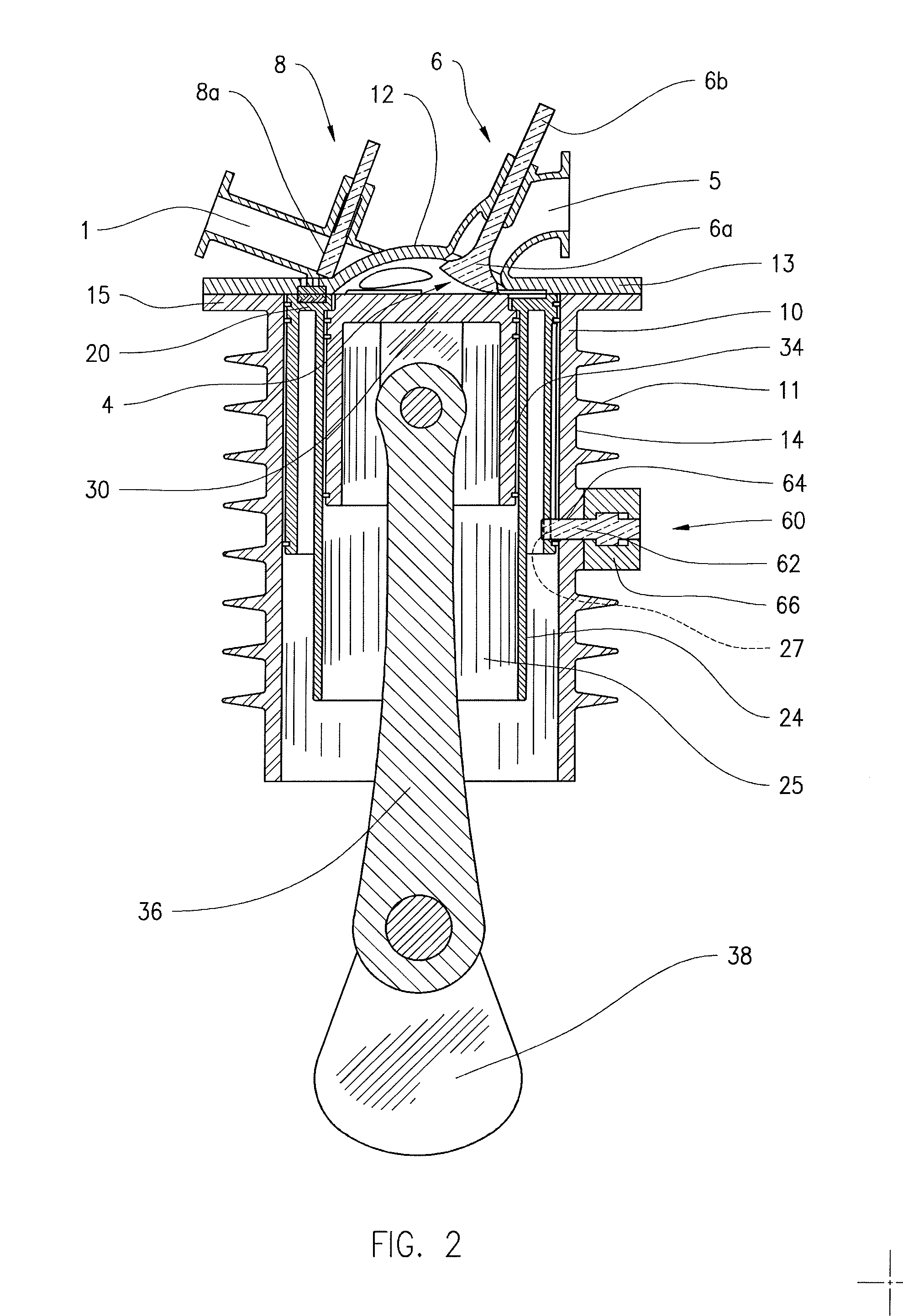
[0027]an engagement means includes a mechanical securement of the outer cylinder 10 to the outer piston 20. FIGS. 2 and 3 show an engaging device 60 disposed in the outer cylinder 10 that selectively engages the outer piston 20 and secures the outer piston 20 to the outer cylinder 10. The engaging device 60 includes a pin 62 that can extend from and between a first position that is out of engagement with the outer piston 20, as shown in FIGS. 7-11, and a second position engaged with the outer piston 20, as shown in FIG. 2-6. The pin 62 engages a bore 27 disposed in the inner cylindrical wall 24 of the outer piston 20. The movement of the pin 62 is an axial movement, inward from the outer cylinder 10. Movement of the pin 62 between the first position and the second position engaged in the bore 35, occurs when the crown 22 of the outer piston 20 is adjacent the cylinder head 12, as shown in FIGS. 2, 6, 7 and 11. FIG. 2-6 shows the pin 62 engaged within the bore 27 with the outer pisto...

second embodiment

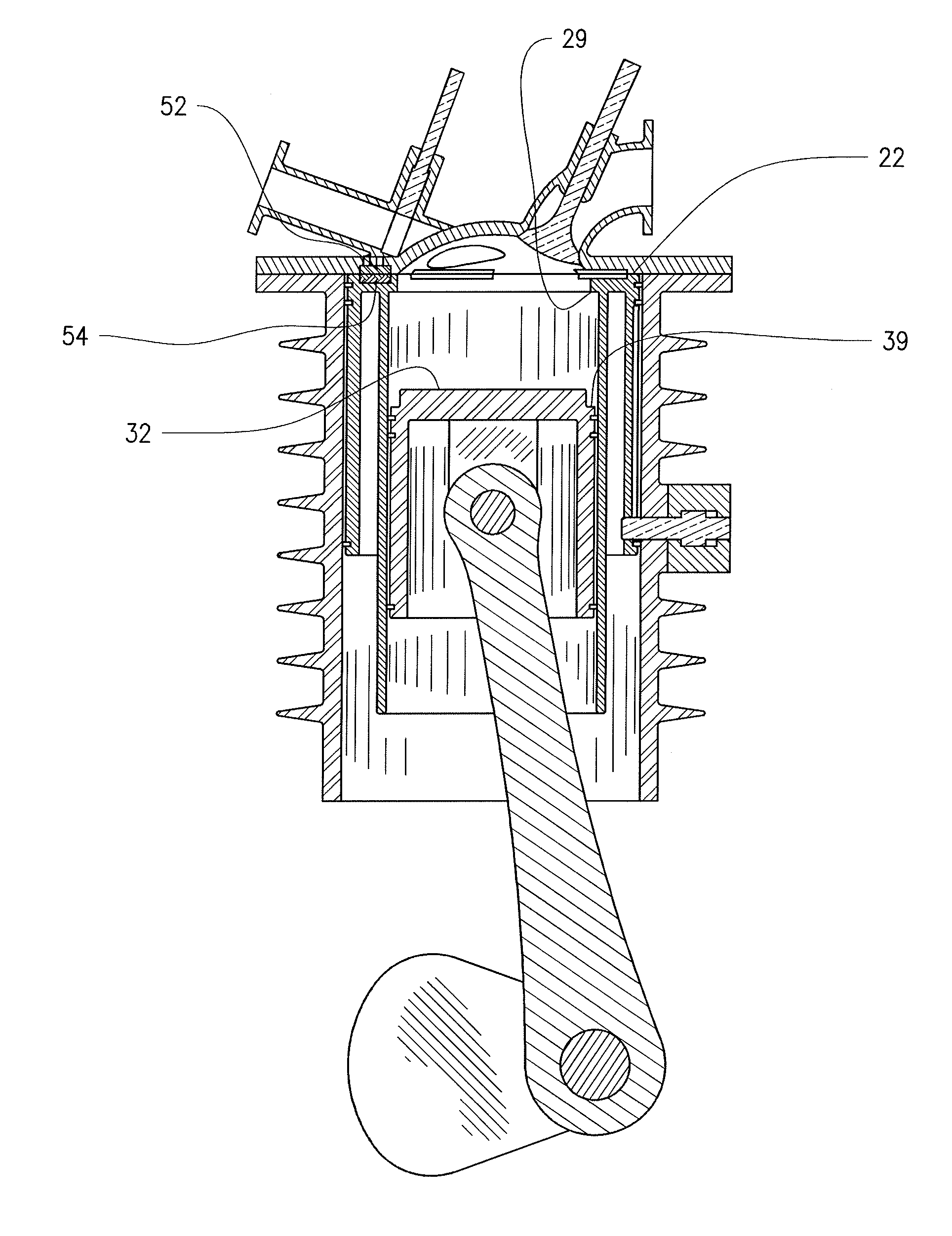
[0029]an engagement means includes a magnet coupling, including a first magnetic member 52 disposed on the underside of the cylinder head 12, and a second magnetic member 54 disposed on the annular crown 22 of the outer piston 20. The first and second magnetic members have magnetically attractive forces when activated which assist to hold the outer piston 20 to the cylinder head 12. The magnetic members can be permanent magnets which exert attractive forces whenever the two magnetic members are in proximity. The magnetic members can also be selectively magnetic, and can include an electromagnetic coupling. Either one of the first or second magnetic members can be the magnetically active member, and the other is the magnetic-attracting member. In the illustrated embodiment, a plurality of the first magnetic members 52 are distributed annularly within the flange of the cylinder head 12, and a corresponding and registering plurality of the second magnetic members 54 are distributed ann...


PUM


Abstract

A cylinder for an internal combustion engine having co-annular dual pistons. The cylinder has a main cylinder having a main cylinder wall and a cylinder head, a first or outer piston having an annular crown, an inner cylinder wall that defines an inner cylinder, and an annular outer sidewall extending from the periphery of the crown, an inner piston having a crown, and an annular inner sidewall extending from the periphery of the crown. A solenoid-actuated pin selectively secures the outer piston with the main cylinder during a portion of each cylinder cycle. The inner piston reciprocates within the inner cylinder during both the air inlet and compression strokes, while the outer piston reciprocates within the main cylinder only during the power stroke and the exhaust stroke, to increase the piston crown surface area exposed to the combustion gases to maximize the power and efficiency.

Description

CROSS REFERENCE TO RELATED APPLICATIONS[0001]This application claims the benefit of U.S. Provisional application 61 / 691,908, filed Aug. 8, 2012, the disclosure of which is incorporated by reference in its entirety.FIELD OF THE INVENTION[0002]The present invention is in the field of internal combustion (IC) engines, and more particularly high efficiency IC engines.BACKGROUND OF THE INVENTION[0003]In a conventional Otto cycle internal combustion (IC) engine, the gasoline fuel is injected into the intake manifold to mix with the air and is drawn into the cylinder through the intake valve during the intake stroke. The fuel flow is metered to produce fuel-air ratios that are very close to stoichiometric for all operating conditions. Conventional IC engines are limited in compression ratio by the requirement that the fuel must be burned at stoicheometric premixed fuel-air ratios with no detonation or pre-ignition, which limits the thermal efficiency that can be achieved with these engines...

Claims


Application Information

Patent Timeline
Patent Type & Authority Applications(United States)
IPC IPC(8): F02F1/24
CPCF02F1/24F02B41/04F02B75/30
Inventor TAYLOR, JACK R.
Owner TAYLOR PATENT HLDG CO LLC
Why Eureka
Try Eureka