Electric Energy Deployment Model for Solar System

a solar system and solar energy technology, applied in emergency power supply arrangements, dc source parallel operation, greenhouse gas reduction, etc., can solve the problems of expensive protection systems, lost size-benefit-effects of isolated systems, and low population density, and achieve the effect of low population density

Inactive Publication Date: 2014-02-27
LIGHTING TAIWAN
View PDF1 Cites 4 Cited by
  • Summary
  • Abstract
  • Description
  • Claims
  • Application Information

AI Technical Summary

Benefits of technology

[0006]Embodiments described herein support a new way of deployment for solar electric energy; aiming at an isolated mid-size power (5 kilowatt to 500 kilowatt) stationary station to capture the opportunity of having size-benefits, while not to inherit most of the cost burdens associated with a centralized photovoltaic solar system. This system is referred as an “isolated centralized solar electric system” herein. At least some of the described embodiments are suitable for solar electric energy deployment in rural areas and many locations in the world where there is plenty of sun-light, spotty housing distribution with very low population density, and / or where there is no expensive power grid due to the expense of the power grid. When coupling with effective lighting elements, it is especially suitable for lightings in these areas.
[0007]This Summary is provided to introduce a selection of concepts in a simplified form that are further described below in the Detailed Description. This Summary is not intended to identify key features or essential features of the claimed subject matter, nor is it intended to be used as an aid in determining the scope of the claimed subject matter.

Problems solved by technology

On the other hand, isolated systems (such as the solar street lamps) are usually small in size and power delivery capacity to increase their affordability, and perhaps because restricted by smaller local energy demand.
Due to their smaller size, the isolated systems usually lose the size-benefit-effects that are present in centralized systems.
However, the providing and maintaining of the centralized system requires payment for equipment for necessary power-conditioning and power-management (including the DC to AC conversion; and voltage and AC phase regulations), providing an expensive protection system to protect valuables (including human lives) from the giant grid-power, and the power grid construction and maintenance.

Method used


Image

  • Electric Energy Deployment Model for Solar System
  • Electric Energy Deployment Model for Solar System
  • Electric Energy Deployment Model for Solar System

Examples


Embodiment Construction

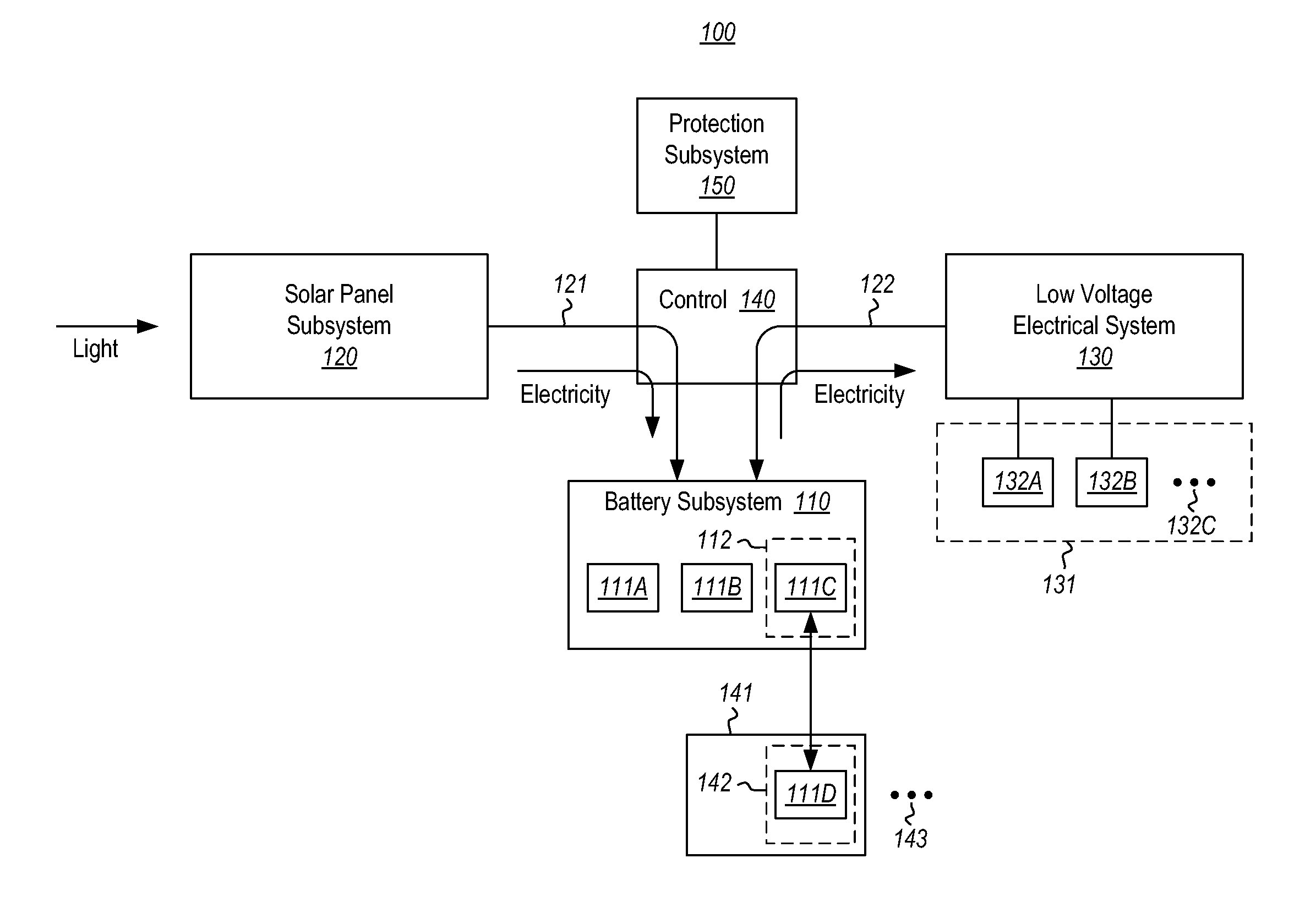
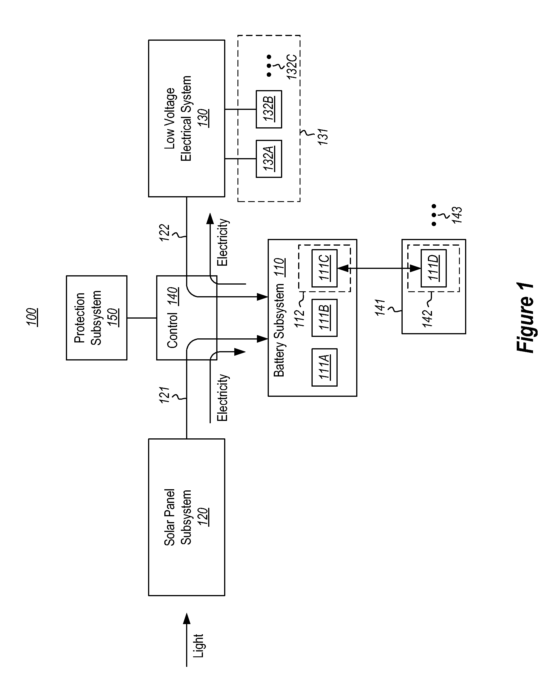
[0011]In accordance with at least one embodiment described herein, an isolated centralized solar electric system (also referred to as the “isolated station” herein) is described. An example embodiment of the isolated station is illustrated in FIG. 1 as element 100. The isolated station is stationary and mid-sized. In this context, a “mid-sized” power station is a stationary power station capable of generating power somewhere in the range of from 5 kilowatts to 500 kilowatts. The isolated station is not connected to a large-scale power grid that spans portions of nations, and even internationally. Instead, the isolated station is coupled to a smaller local power grid.

[0012]Thus, while the mid-sized isolated station is similar to a centralized station in that it is stationary, the mid-sized power station is much different than the centralized station in that the isolated station is orders of magnitude smaller and is coupled only to a local power grid.

[0013]The isolated centralized sol...


PUM


Abstract

An isolated mid-sized centralized photovoltaic solar station that includes a solar panel subsystem that converts photon energy into electricity, and a battery subsystem an energy reservoir to store electrical energy generated by the solar panel subsystem. A control unit regulates the output of energy from the solar panel system onto a low voltage electrical system that provides electrical power to electricity consuming devices or systems. The electrical system may operate at less than 50 volts thereby make the protection system less expensive. Furthermore, some of the batteries in the station may be mobile, so that they can be transported and used external to the station.

Description

CROSS-REFERENCE TO RELATED APPLICATIONS[0001]The present application is a continuation-in-part of U.S. patent application Ser. No. 13 / 592,221 filed Aug. 22, 2012, which is incorporated herein by reference in entirety.BACKGROUND[0002]Photovoltaics involve directly converting light energy from incident photons into electricity. Photovoltaic systems for electric power generation are in commercial use (referred as “solar electric systems” herein). The solar electric systems receive energy from the sun-light at photovoltaic solar panels, whereupon the panels directly convert the photons into electricity.[0003]There are generally two categories of photovoltaic energy deployment in common practice today. In a first category, the photovoltaic system is used as a power source supplying electricity to the power grid. In order to connect to the power grid, adjustments are required such as, for example, Direct Current (DC) to Alternating Current (AC) conversion, voltage regulation, and phase re...

Claims


Application Information

Patent Timeline
Patent Type & Authority Applications(United States)
IPC IPC(8): H02J1/00
CPCH02J1/00H02J3/32H02J7/35Y02E70/30H02J2300/24H02J3/381Y02E10/56
Inventor SHUY, GEOFFREY WEN-TAILIAO, JAU-DARLI, CHANG-HORANG
Owner LIGHTING TAIWAN
Why Eureka
Try Eureka