Linear motor

Active Publication Date: 2014-02-27
SANYO DENKI CO LTD
View PDF4 Cites 15 Cited by
  • Summary
  • Abstract
  • Description
  • Claims
  • Application Information

AI Technical Summary

Benefits of technology

[0019]In the linear motor according to the present invention, a plurality of cooling pipes having a meander shape is arranged in the core along the longitudinal direction, and these pipes are connected in parallel. Therefore, the linear motor can prevent the increase in the total length of each cooling pipe. And, since the cross-sectional area of the refrigerant flow path can be doubled, the pressure loss of the refrigerant can be reduced.
[0020]Also, in the linear motor according to the present invention, the cooling pipes vertically adjacent to each other are arranged such that in

Problems solved by technology

However, since this linear motor according to Patent Document 1 has a large number of components forming the cooling structure, the production cost is increased, and it is difficult to realize high assembling precision.
However, in the armature for the linear motor according to Patent Document 2, the cooling pipe is long, so the pressure loss

Method used


Image

  • Linear motor
  • Linear motor
  • Linear motor

Examples


first embodiment

[0039][Configuration of Linear Motor]

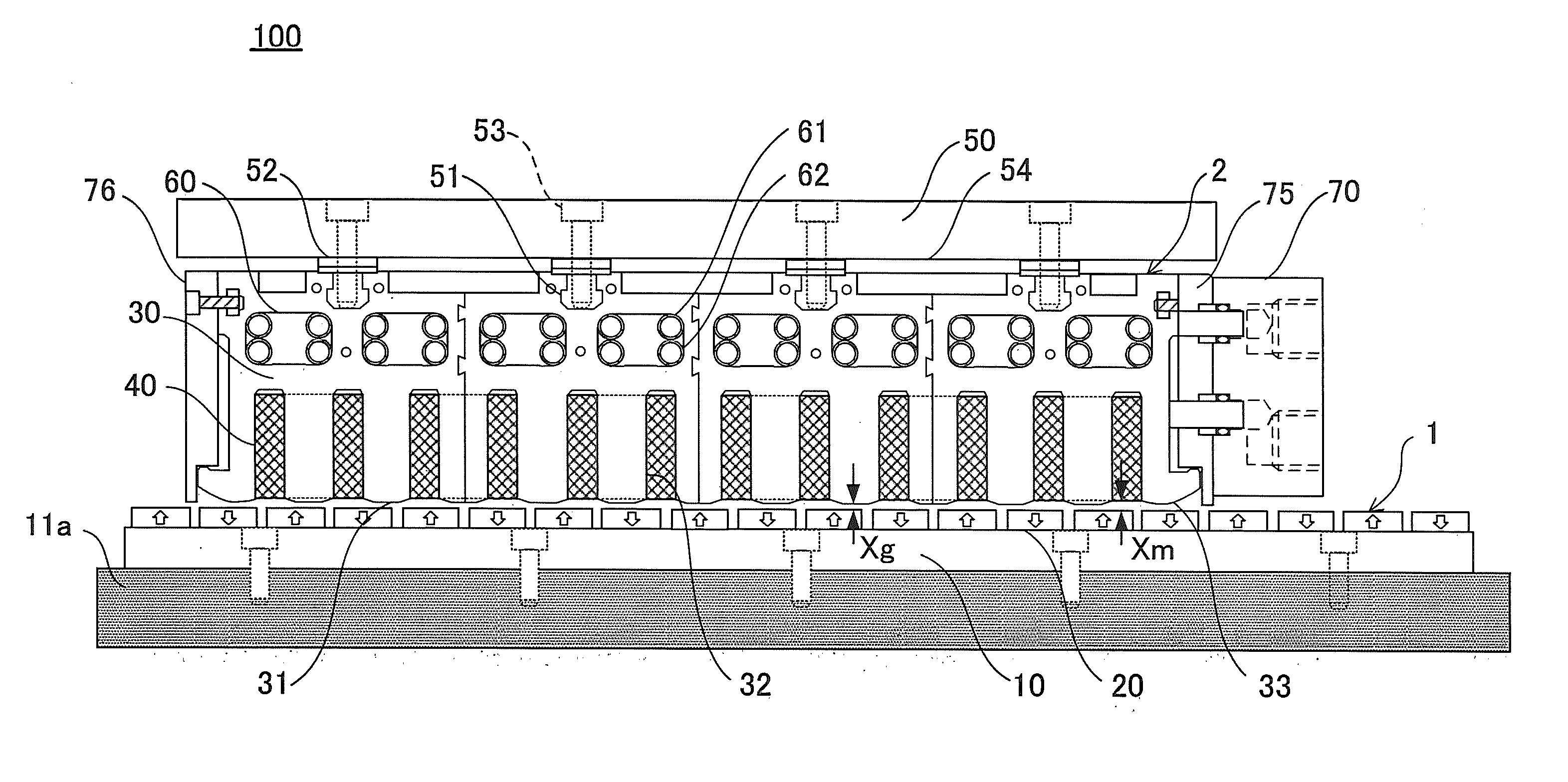
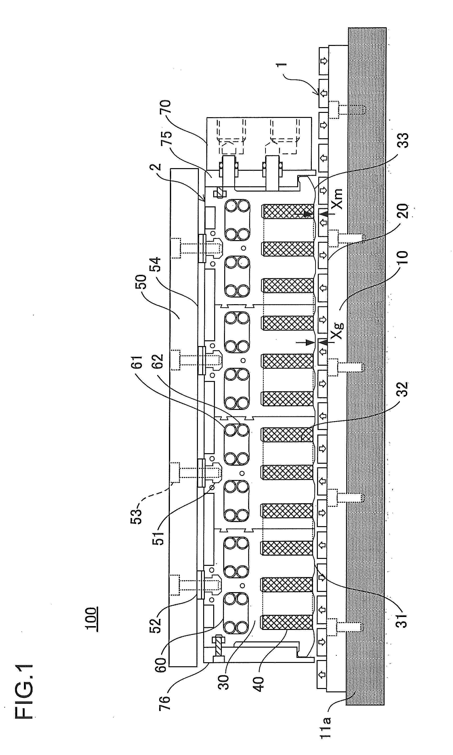
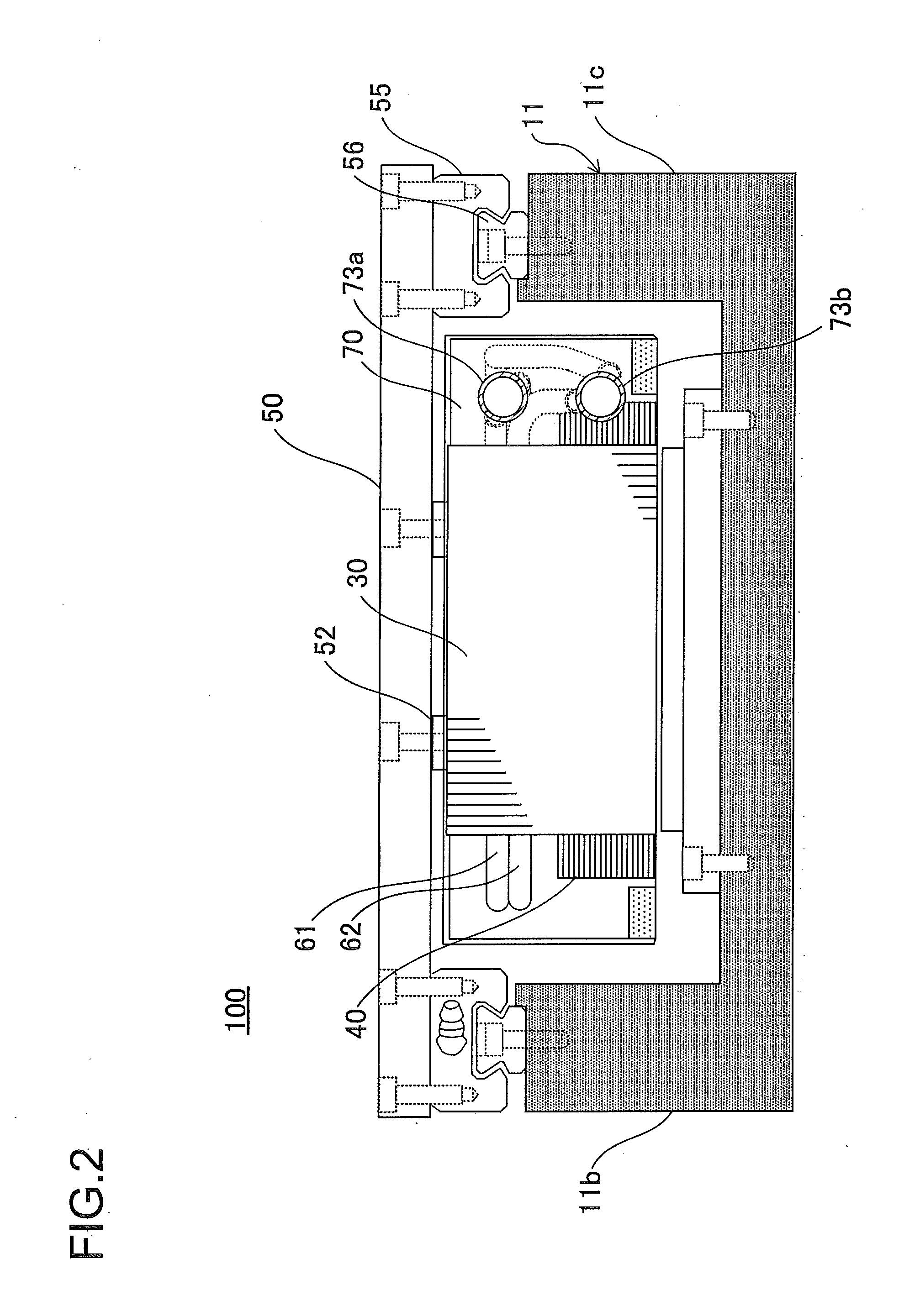
[0040]A configuration of a linear motor according to the first embodiment will firstly be described with reference to FIGS. 1 and 2. FIG. 1 is a cross-sectional view illustrating a linear motor along a longitudinal direction according to the first embodiment. FIG. 2 is a right side view of the linear motor according to the first embodiment.

[0041]As illustrated in FIGS. 1 and 2, a linear motor 100 according to the first embodiment includes a field unit 1 and an armature 2.

[0042]The field unit 1 includes a yoke 10 and permanent magnets 20.

[0043]The yoke 10 is a plate-like magnetic metal member. The yoke 10 is fixed on a bottom 11a of a mounting base 11 having a squared U-shaped cross-section. The field unit 1 functions as a stator.

[0044]The yoke 10 has a function of maximizing an electromagnetic induction effect of the permanent magnets 20 by closing a magnetic line directed from the field unit 1 to the mounting base 11. The material of the yoke 10...

second embodiment

[0092]Next, the second embodiment will be described with reference to FIGS. 8A to 8D. FIGS. 8A to 8D are schematic cross-sectional views illustrating an example of an arrangement of the cooling pipes according to the second embodiment. The components same as those in the linear motor 100 in the first embodiment are identified by the same numerals, and the description will be omitted.

[0093]As illustrated in FIGS. 8A to 8D, the arrangement of the cooling pipes 61 and 62 in the second embodiment is different from that in the first embodiment.

[0094]In the arrangement example of the second embodiment, the upper cooling pipe 61 and the lower cooling pipe 62 are in contact with each other in the cooling pipe storage hole 60, and a heat transfer material 81 having high heat conductivity is provided in a space between the cooling pipes 61 and 62. As a material for the heat transfer material 81, a material with high heat conductivity including copper, aluminum, and graphite etc. can be employ...

third embodiment

[0102]Next, a third embodiment will be described with reference to FIGS. 9A to 9F. FIGS. 9A to 9F are schematic cross-sectional views illustrating an example of an arrangement of the cooling pipes according to the third embodiment. The components same as those in the linear motor 100 in the first embodiment are identified by the same numerals, and the description will be omitted.

[0103]As illustrated in FIGS. 9A to 9F, the arrangement of the cooling pipes 61 and 62 in the third embodiment is different from that in the first embodiment.

[0104]As described with reference to FIG. 7B, the cooling pipes 61 and 62 easily transfers heat to the refrigerant to attain effective cooling when they are brought into contact with each other, but they also easily transfer heat to the movable stage 50. In order to prevent the heat transfer to the movable stage 50, the upper cooling pipe 61 and the lower cooling pipe 62 are arranged to be separate from each other within the cooling pipe storage hole 60...


PUM


Abstract

An armature of a linear motor includes a plurality of cooling pipe storage holes formed along a longitudinal direction of a core, and a plurality of cooling pipes stored vertically in the cooling pipe storage holes and having a meander shape. The cooling pipes vertically adjacent to each other are arranged such that inlets and outlets of the cooling pipes are alternately connected in parallel to a refrigerant inlet and a refrigerant outlet in order to allow a refrigerant to flow in the reverse direction.

Description

BACKGROUND[0001]1. Technical Field[0002]The present invention relates to a linear motor that causes a linear motion to an object to be driven using electromagnetic force, and more particularly to a linear motor having a cooling structure.[0003]2. Description of Related Arts[0004]In general, a linear motor includes a field unit having a plurality of permanent magnets which are arranged such that the adjacent polarities are different from each other, and an armature which has a coil arranged opposite to the permanent magnets and which is capable of sliding in a longitudinal direction of the field unit.[0005]In the linear motor, current flows through the coil of the armature so as to cross magnetic flux generated by the permanent magnets of the field unit, whereby driving force is generated on the coil in the longitudinal direction by electromagnetic induction to move the armature.[0006]Since the coil generates heat during the operation of the linear motor, it is necessary to prevent t...

Claims


Application Information

Patent Timeline
IPC IPC(8): H02K9/20H02K41/02
CPCH02K41/02H02K9/20H02K41/031H02K1/20H02K2213/03
Inventor SUGITA, SATOSHIMISAWA, YASUSHIMIYAIRI, SHIGENORI
Owner SANYO DENKI CO LTD
Why Eureka
Try Eureka