
White Light Illumination System with Narrow Band Green Phosphor and Multiple-Wavelength Excitation

Active Publication Date: 2014-02-27
INTEMATIX
View PDF0 Cites 69 Cited by
  • Summary
  • Abstract
  • Description
  • Claims
  • Application Information

AI Technical Summary

Benefits of technology

The present invention is about illumination systems that use a multi-chip excitation source and a phosphor package to produce white light. The phosphor package comprises a narrow band green phosphor that emits photoluminescence in a specific range of wavelengths. The illumination system includes a first and second radiation source that provide co-excitation radiation to the phosphor package. The narrow band green phosphor is designed to have a photoluminescence peak with a full width at half-maximum of less than 60 nm. The technical effect of this invention is to produce a high-quality white light with a narrow band green phosphor that has a long-lasting, stable photoluminescence peak.

Problems solved by technology

Economically, white LED's have the potential to replace incandescent light sources (light bulbs), particularly as production costs fall and the technology develops further.
The benefits of these single-chip systems are well appreciated in the art, but so too are their drawbacks when it comes to enhancing color rendering properties.
For example, the white light emission from a typical one-chip system consisting of a blue LED and a yellow phosphor (such as YAG:Ce) is deficient in the longer wavelength side of the visible spectrum, resulting in a bluish white light appearance.
The YAG:Ce yellow phosphor of the system does not help much in contributing to the needed 600 to 700 nm emission content, since its excitation band with the greatest efficiency is at about 460 nm, and the excitation range of this yellow phosphor is not particularly broad.
Further disadvantages of this single-chip system are the disparities in the emission wavelength ranges of the blue LED, due in part to the manufacturing process, and if these deviate from the optimal excitation range of the YAG:Ce-based yellow phosphor, there results a loss of wavelength balance between the blue light and the yellow light.
There are also disadvantages to this second category of single-chip systems.
The white LED designer therefore may have little choices available other than to increase the ratio of the red phosphor in the mixture relative to the blue and green phosphors.
But this action may lead to an undesirable consequence: the ratio of the green phosphor to the others may now be insufficient and luminescence from the white LED may suffer.
It would appear that a white color with high luminescence is difficult to obtain.
And the color rendering properties are still nowhere near optimum as the red phosphor typically has a sharper emission spectrum than the others.
It is clear that multi-chip white light illumination systems suffer from disadvantages, not the least of which is a need for a plurality of voltage control systems and the increased heat production from the many individual chips needed to produce the white light's component colors.
But each of the single-chip systems have their problems too, perhaps most notably being the inability to achieve an acceptable color rendering outcome.

Method used


Image

  • White Light Illumination System with Narrow Band Green Phosphor and Multiple-Wavelength Excitation
  • White Light Illumination System with Narrow Band Green Phosphor and Multiple-Wavelength Excitation
  • White Light Illumination System with Narrow Band Green Phosphor and Multiple-Wavelength Excitation

Examples


second embodiment

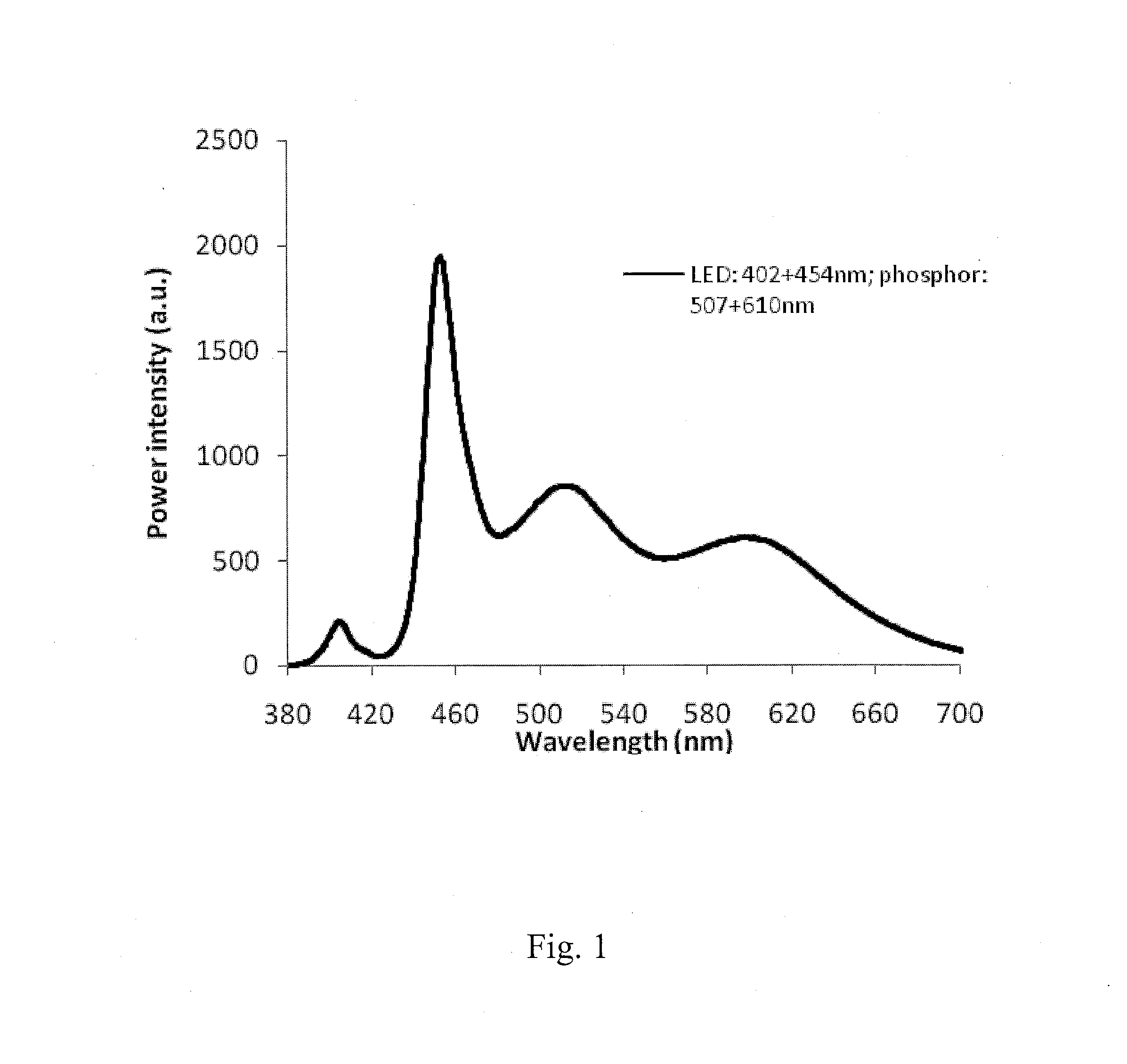
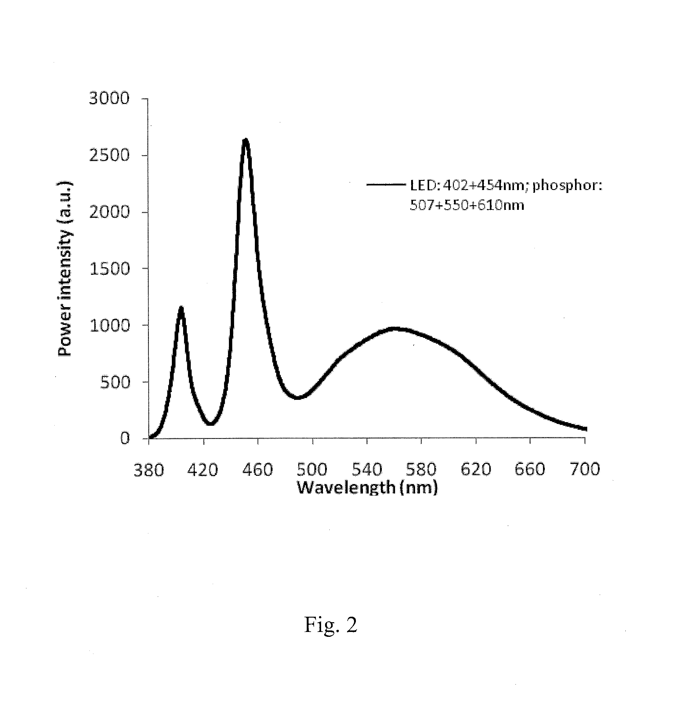
[0052]Unlike the first example that involved a mixture of two phosphors, in this second embodiment with a three-phosphor mixture in the phosphor package, there is created an essentially infinite number of blending ratios that can achieve the same target CIE. Generally, the addition of a yellow phosphor provided the advantage on high brightness, while the green and orange phosphors work advantageously to increase the CRI. In other words, optimization of the CRI value and the brightness may be achieved separately by fine tuning the ratio of the yellow phosphor concentration to that of the orange and green phosphors.

[0053]In the third example, a blue phosphor designated B450 was added to the green, yellow, and orange mix (G507, Y550, O610, respectively) discussed in the second example. FIG. 3 shows the emission spectrum from a white LED utilizing the same UV and blue LED chip sources as in the first and second examples (402 nm and 454 nm). The brightness was 23.62, the CRI 89.1. The bl...

sixth embodiment

[0058]The multi-chip excitation source in the first five examples was either a UV / blue combination or a purple / blue combination. High brightness, high CRI white light illumination sources can be provided by using a blue chip and green chip with a phosphor package having two phosphors in one embodiment, and three phosphors in another. These phosphors can be any combination of a green phosphor such as G530, a yellow phosphor such as Y550), an orange phosphor such as O590, and a red phosphor such as R662. In this sixth example, the chip set was a blue LED in combination with a green LED. So in example three the white LED comprised a first radiation source emitting light in wavelength ranging from 440 to 480 nm, and a second radiation source co-exciting a phosphor package, the second radiation source emitting light in wavelengths ranging from 480 to 540 nm. This chip set provided co-excitation radiation to at least two types of phosphors emitting light in wavelength range from 500 to 70...


PUM


Abstract

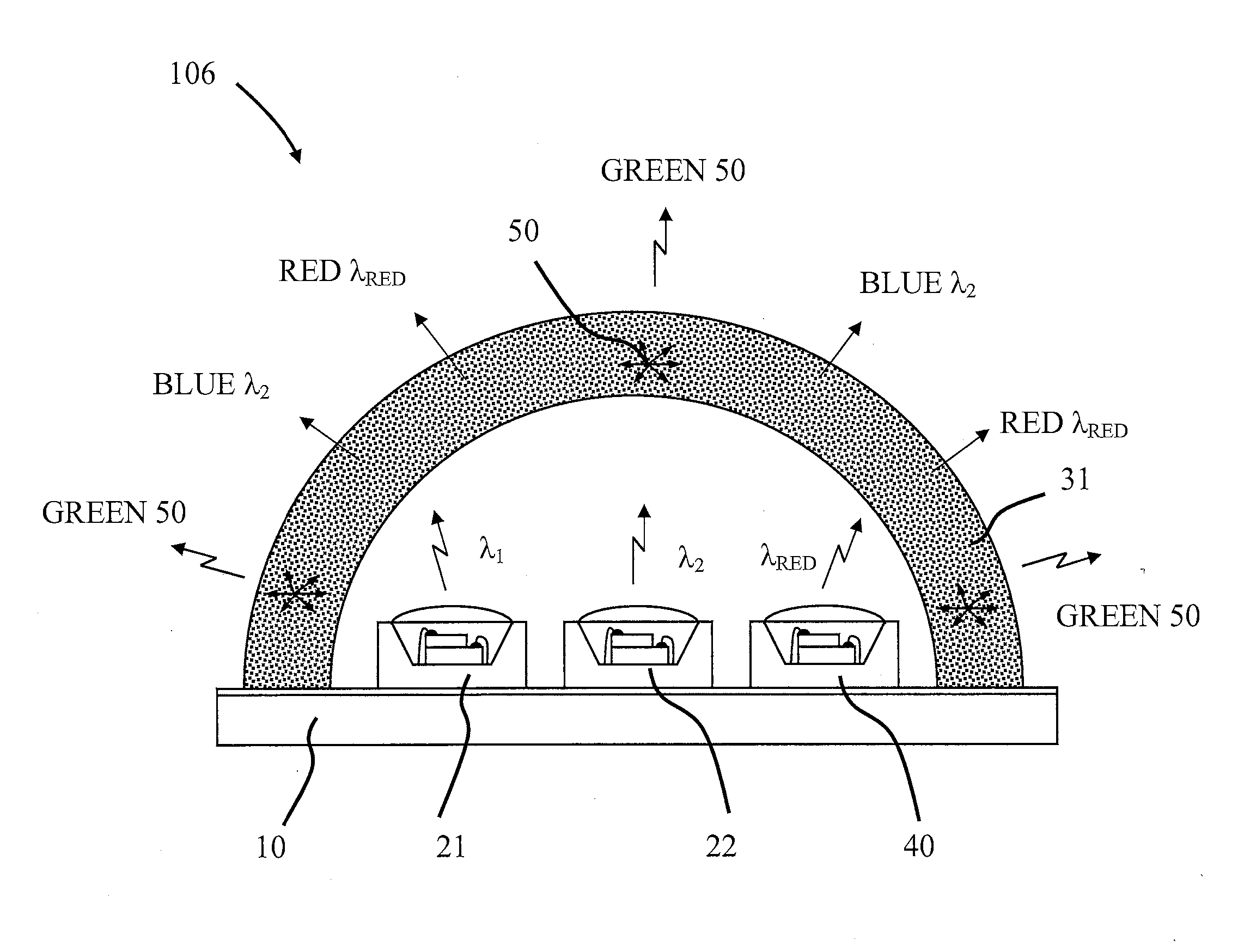
A white light illumination system may comprise: a phosphor package; a first radiation source for providing co-excitation radiation to the phosphor package, the source emitting in wavelengths ranging from about 250 nm to about 410 nm; and a second radiation source for providing co-excitation radiation to the phosphor package, the source emitting in wavelengths ranging from about 410 nm to about 540 nm; wherein the phosphor package is configured to emit photoluminescence in wavelengths ranging from about 440 nm to about 700 nm upon co-excitation from the first and second radiation sources, and wherein the phosphor package comprises at least one narrow band green phosphor with a photoluminescence peak with a full width at half maximum of less than 60 nm, and wherein the narrow band green phosphor is configured to emit photoluminescence in wavelengths ranging from about 500 nm to about 550 nm.

Description

CROSS REFERENCE TO RELATED APPLICATIONS[0001]This application is a continuation-in-part of U.S. patent application Ser. No. 12 / 398,059 filed Mar. 4, 2009, which claims the benefit of priority to provisional application Ser. No. 61 / 034,699 filed Mar. 7, 2008, which applications are incorporated herein by reference in their entirety.FIELD OF THE INVENTION[0002]Embodiments of the present invention are directed in general to white light illumination systems with phosphor material including a narrow band green phosphor and multiple radiation sources for co-excitation of the phosphor material. More particularly, though not exclusively, embodiments of the invention concern white light illumination systems for color liquid crystal displays.BACKGROUND OF THE INVENTION[0003]Devices known as “white LED's” are relatively recent innovations designed to replace the conventional incandescent light bulb. It was not until LED's emitting in the blue / ultraviolet region of the electromagnetic spectrum ...

Claims


Application Information

Patent Timeline
IPC IPC(8): F21V9/16F21V33/00
CPCF21V33/0052F21V9/16C09K11/0883C09K11/7733C09K11/7734C09K11/7739C09K11/7774H01L25/0753H01L33/504H01L2224/48091H01L2924/0002F21K9/64F21Y2115/10Y02B20/00C09K11/77344C09K11/77342C09K11/77348H01L2924/00014H01L2924/00
Inventor TAO, DEJIELI, YI-QUNWANG, GANG
Owner INTEMATIX
Learn More