Fluid delivery apparatus with flow rate sensing means

a flow rate sensing and flow rate technology, applied in process and machine control, electrical control of exhaust treatment, instruments, etc., can solve the problems of inability to effectively remove oxidative specie nox, inability to control the delivery pressure, and difficulty in measuring the actual delivery amount of the first fluid

Inactive Publication Date: 2014-03-06
YAN MI +1
View PDF8 Cites 29 Cited by
  • Summary
  • Abstract
  • Description
  • Claims
  • Application Information

AI Technical Summary

Benefits of technology

[0011]The present invention provides a fluid delivery apparatus, which delivers a first fluid into a second fluid, with a multifunctional sensing means that is able to provide information of fluid delivery rate in an apparatus using the pump metering method, and information of fluid delivery rate, flow rate and temperature of the second fluid, and evaporation rate of the first fluid in an apparatus using the common rail method. In an embodiment of the present invention, the fluid delivery apparatus is a reductant delivery apparatus in an exhaust gas treatment system of an internal combustion engine. The reductant delivery apparatus uses the common rail method, in which the average reducant dosing rate is controlled by using a PWM (Pulse Width Modulation) method that generates a pulsated reductant flow by operating an injector on or off. A hot wire sensor which includes a cold wire sensing piece installed upstream of the injector of the reductant delivery apparatus and a hot wire sensing piece positioned in the spray path of the reductant released from the injector. The cold wire sensing piece is used to sense the temperature of exhaust flow and the hot wire sensing piece together with the cold wire sensing piece are used to provide a sensing signal indicative of exhaust flow rate during off-time of the injector. During on-time of the injector the sensing value obtained from the hot wire sensing piece is a function of exhaust flow rate and temperature, reductant evaporating rate, and reductant delivery rate, and in the transition from on-time to off-time, the change in the sensing value is affected by reductant delivery rate, exhaust flow, and exhaust temperature. By using the signals provided by the hot wire and the cold wire sensing pieces, the values of exhaust flow rate, reducant dosing rate that includes both peak dosing rate and average dosing rate, on-time and off-time of the injector, and exhaust temperature, and an evaporation value can be obtained. With the reductant dosing rate value provided by the hot wire sensor, a feedback control can be used to adjust a reductant dosing command generated according to a target value. The evaporation value is indicative of the evaporation capability of the reductant in exhaust flow, therefore, it can be used to determine the maximum allowed dosing rate, so that only the amount of the reductant that is able to evaporate is released to exhaust gas. The values of exhaust flow rate, peak dosing rate, and on-time and off-time of the injector provide information about the components in the exhaust gas treatment system. This information can be used in rationality check for these components, which is required in a diagnostic system such as an OBD (On-Board Diagnostic) system. Additionally, the values of exhaust flow rate and exhaust temperature can also be used in calculating air enthalpy change in an engine, which is then an indication of abnormalities of the exhaust gas treatment system including leakage and mal-position.

Problems solved by technology

In a fluid delivery apparatus with metering pump, however, since the metering pump is for controlling delivery amount of the first fluid, delivering pressure is not controlled.
In lean combustion engines, due to the existence of large amount oxygen excess, passive means without extra dosing agents, such as a three-way catalyst apparatus used commonly in spark-ignition engines, normally are not able to effectively remove the oxidative specie NOx.
This type of fluid delivery creates a difficulty in measuring actually delivered amount of the first fluid in the second fluid.
Another difficulty in measuring actually delivered first fluid is caused by the harsh environment in the second fluid.
In such an environment, it is difficult to position a normal flow sensor in the second fluid.
The lack of sensing means that is able to measure the actually delivered first fluid results in that the delivery accuracy relies on the performance and reliability of the delivery components in the fluid delivery apparatus, since errors caused by the delivery components cannot be compensated in system level.
In the evaporation process, if the second fluid is not able to provide enough thermal energy, then the first fluid may condense and cause issues.

Method used


Image

  • Fluid delivery apparatus with flow rate sensing means
  • Fluid delivery apparatus with flow rate sensing means
  • Fluid delivery apparatus with flow rate sensing means

Examples


Embodiment Construction

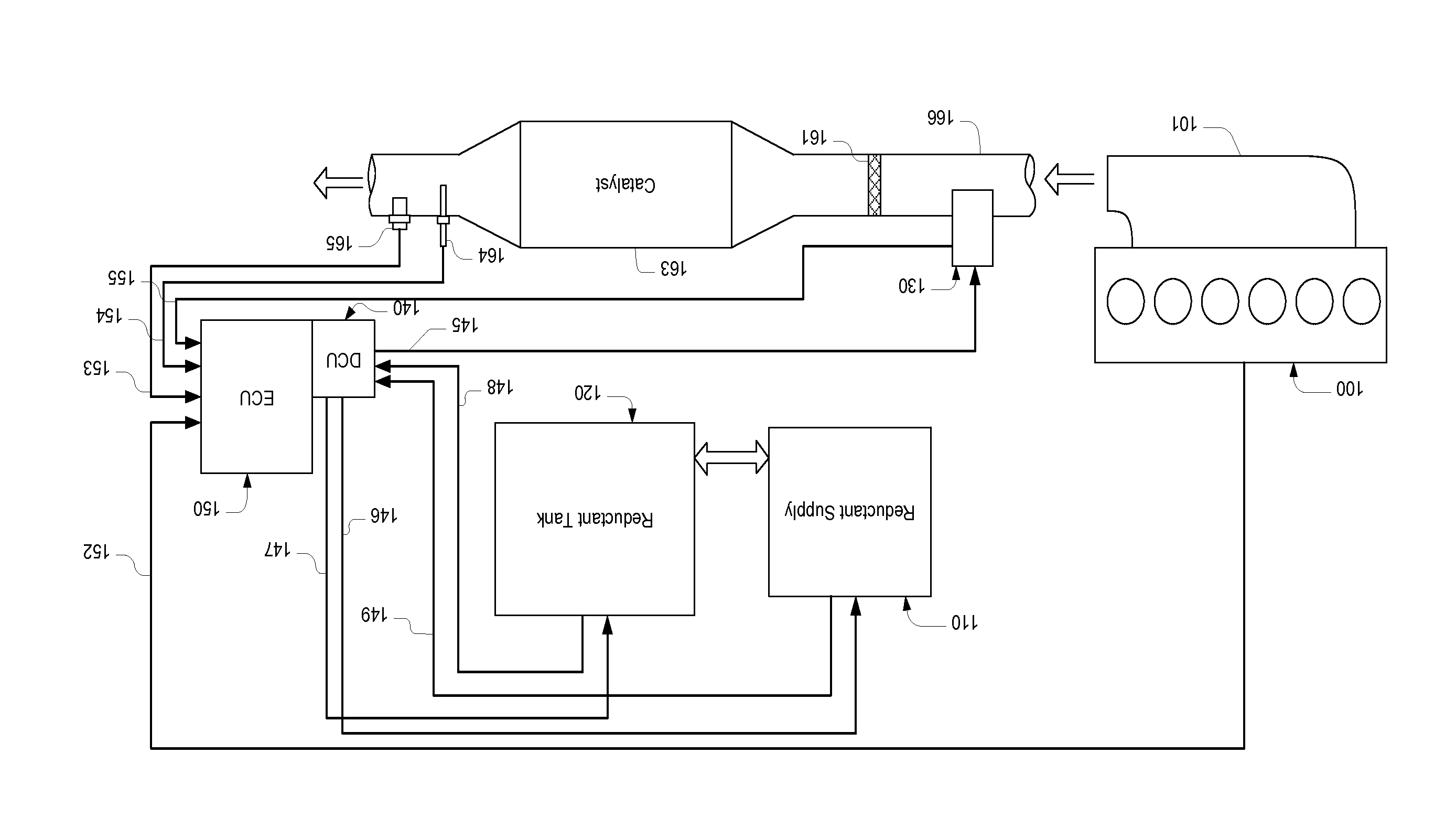
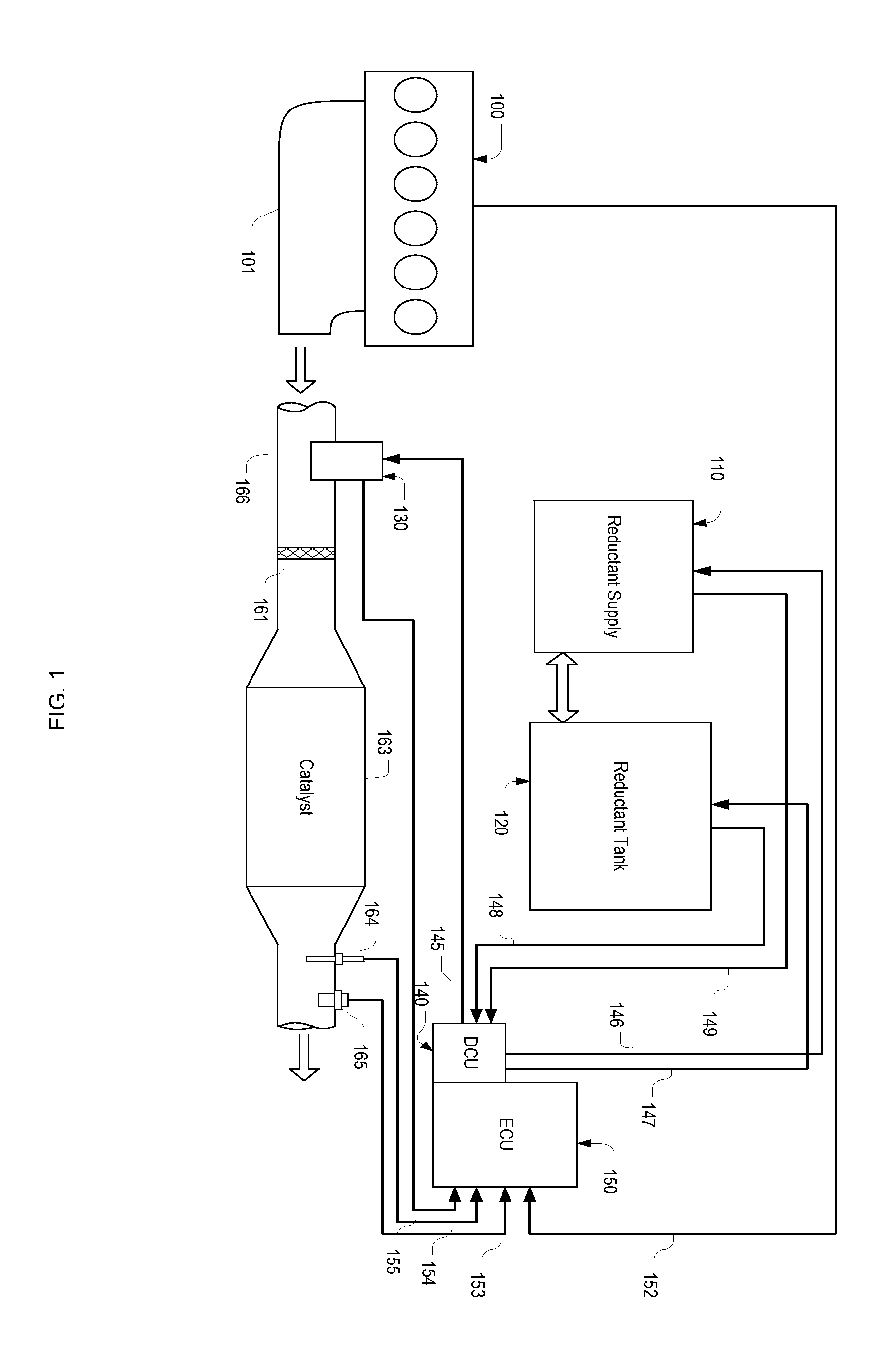
[0030]Referring to FIG. 1, in an engine exhaust gas treatment system, exhaust gas generated by an engine 100 enters a passage 166 through a manifold 101. On the passage 166, a reductant injection module 130 is installed. The injection module 130 is controlled by a DCU (Dosing Control Unit) 140 through signal lines 145 and sensing information obtained from the injection module is sent to an ECU (Engine Control Unit) via signal lines 155. Reductant is supplied to the injection module 130 by a reductant supply module 110, which is controlled by the DCU through signal lines 146, and draws reductant from a tank 120, the heating of which is controlled by the DCU through signal lines 147. Sensing information, such as reductant temperature and pressure, obtained in the reductant supply module is sent to the DCU via signal lines 149, while sensors in the reductant tank, e.g., tank temperature sensors and level sensors, report values to the DCU through signal lines 148. The reductant injected...


PUM


Abstract

A fluid delivery apparatus with a flow sensing means for delivering a first fluid into a second fluid. In a fluid delivery apparatus using a common rail method, which produces a pulsated flow, the flow sensing means generates sensing signals indicative of the flow rate and the temperature of the second fluid, the delivery rate of the first fluid, and the evaporating rate of the first fluid, while in a fluid delivery apparatus using a pump metering method, the flow sensing means is able to provide a sensing signal indicative of the delivery rate of the first fluid. The sensing signals can be used in a feedback control for controlling delivery rate, in limiting delivery rate according to the evaporation capability of the first fluid, and in a diagnostic system detecting failures and abnormalities in the fluid delivery apparatus.

Description

FIELD OF THE INVENTION[0001]The present invention relates to a fluid delivery apparatus for delivering a first fluid into a second fluid, more particularly, to a fluid delivery apparatus with a flow rate detection means for metering and delivering a first fluid into a flow of a second fluid.BACKGROUND OF THE INVENTION[0002]In mixing two fluids together to create a mixture with the amount of a first fluid precisely controlled, normally a fluid delivery device is needed for metering and delivering the first fluid into a second one. Metering methods in the fluid delivery apparatus include a pump metering method, in which a metering pump is used to precisely control the amount of the first fluid to be delivered, and a common rail method, in which the first fluid is contained in a common rail or a buffer chamber with its pressure controlled higher than that of the second fluid, and the metering is achieved by controlling the open time of a nozzle fluidly connected to the common rail. To ...

Claims


Application Information

Patent Timeline
Patent Type & Authority Applications(United States)
IPC IPC(8): F01N9/00F01N11/00G05D11/13
CPCF01N3/208F01N11/00F01N2560/07F01N2560/20F01N2610/02F01N2610/148F01N2900/0416F01N2900/12F01N2900/1411F01N2900/1811F01N2900/1812G05D7/0635Y02T10/12Y02T10/40Y10T137/2499Y10T137/6606
Inventor YAN, MIQI, BAOHUA
Owner YAN MI
Why Eureka
Try Eureka