Supercharge Your Innovation With Domain-Expert AI Agents!

Exhaust Gas Recirculation Apparatus and Method for Forming Same

a technology of exhaust gas recirculation and cooler, which is applied in the direction of combustion air/fuel air treatment, lighting and heating apparatus, machines/engines, etc., can solve the problems of affecting the overall affecting the performance of the engine, and affecting the overall engine performance. , to achieve the effect of limiting mechanical stresses

Active Publication Date: 2014-03-06
SENIOR IP GMBH
View PDF3 Cites 19 Cited by
  • Summary
  • Abstract
  • Description
  • Claims
  • Application Information

AI Technical Summary

Benefits of technology

The patent describes an improved exhaust gas recirculation cooler for use in engines. The cooler has flexible sections that allow it to expand and contract with changes in temperature, which reduces mechanical stresses on the end plates and ensures proper functioning of the cooler. The cooler is made up of multiple tubes with flexible sections that displace independently of each other, minimizing mechanical stress and enhancing durability. The overall design of the cooler reduces wear and tear and improves the longevity of the cooler system.

Problems solved by technology

Exhaust gas recirculation coolers have proven to be some of the most complex and historically unreliable pieces of a modern internal combustion engine.
Thermal shock refers to abnormal operating conditions of exhaust gas recirculation coolers, such as the loss of coolant through broken pumps, cooling line failure, etc.
Metal expansion during thermal shock in an exhaust gas recirculation cooler may cause the exhaust gas recirculation cooler to rupture or leak, which, in turn, may negatively impact the overall engine performance.
With a cooler leak, coolant may enter the path of the recirculated exhaust gas—back into the intake manifold and, ultimately, the engine cylinder.
Any coolant in the engine cylinders impedes the engine's performance and, at certain levels, may completely inhibit the cylinders from firing.
Furthermore, if coolant is leaking out of an exhaust gas recirculation cooler, the engine's overall cooling system is affected by that coolant loss.
As set forth above, an elevated temperature of the combustion mixture may lead to undesirable engine and emissions performance.
However, such hollow, round, corrugated tubes have power density limitations, that is, a relatively limited ability to cool exhaust gases passing therethrough, for a given size of tube, as compared to other known constructions for cooler tubes.
Such a macro-compensating feature is limited in its effectiveness, however, as exhaust gas recirculation coolers typically do not experience thermal shock on a uniform, macro-scale.
Rather, thermal shock conditions typically result in non-uniform expansion of cooling tubes.

Method used


Image

  • Exhaust Gas Recirculation Apparatus and Method for Forming Same
  • Exhaust Gas Recirculation Apparatus and Method for Forming Same
  • Exhaust Gas Recirculation Apparatus and Method for Forming Same

Examples


Embodiment Construction

[0044]The present disclosure is further described with reference to the accompanying drawings, which show particular embodiments of the disclosure. However, it should be noted that the accompanying drawings are merely exemplary. For example, the various elements and combinations of elements described below and illustrated in the drawings can vary to result in embodiments which are still within the spirit and scope of the present disclosure.

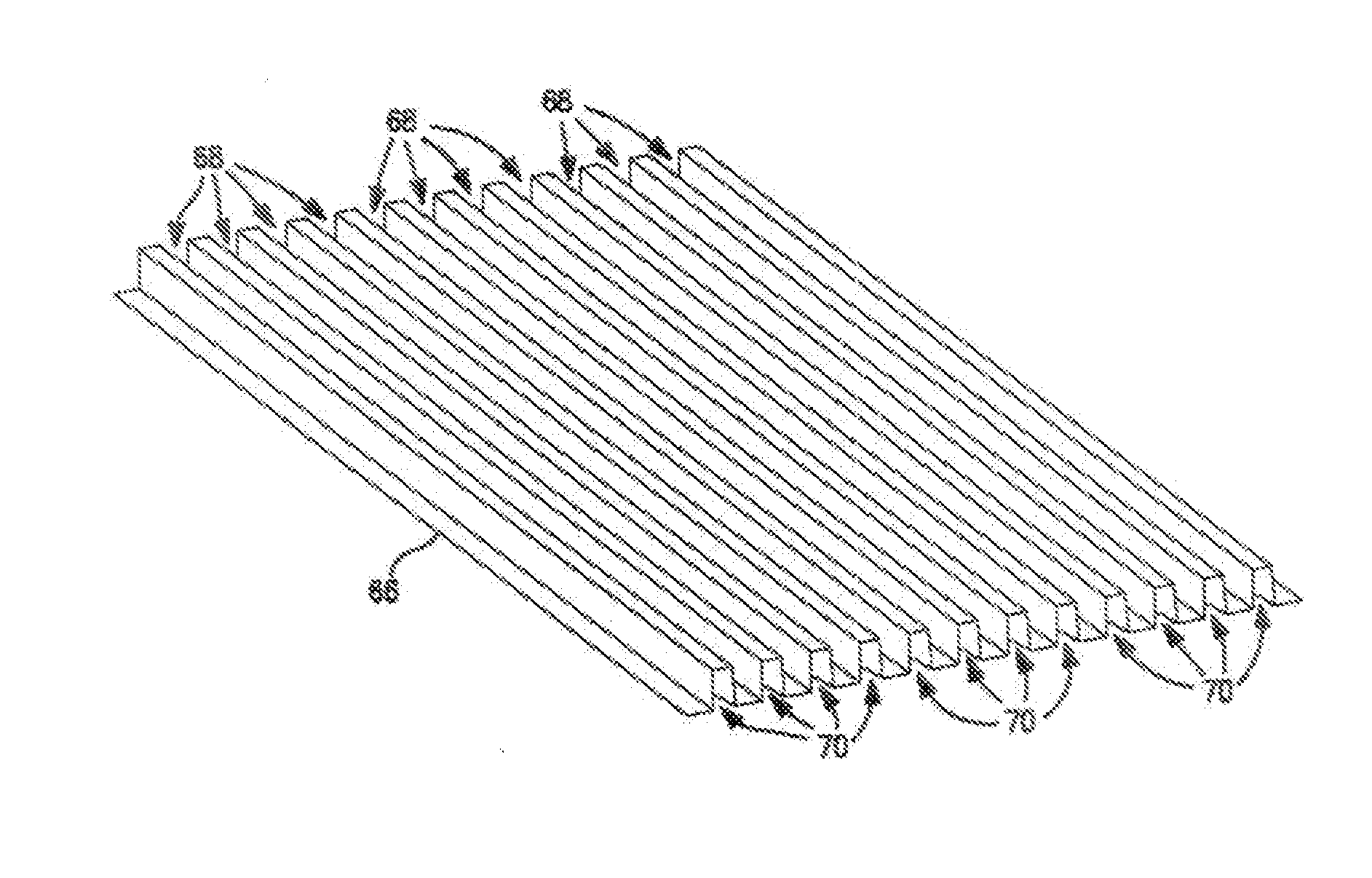
[0045]With reference to FIGS. 8-10, exemplary exhaust gas recirculation cooler 20 includes main body 22 and first and second end plates 24, 26 encasing cooler tube assemblies 30, which are arranged in an array in the illustrated embodiment. Exhaust gas recirculation cooler 20 is capable of being coupled to the exhaust manifold of an internal combustion engine via exhaust inlet 36, and is configured to direct the exhaust gases back toward the engines intake manifold via exhaust outlet 38, after the exhaust gases pass through cooler tube assemblies ...


PUM

PropertyMeasurementUnit
Thicknessaaaaaaaaaa
Flexibilityaaaaaaaaaa
Mechanical propertiesaaaaaaaaaa

Abstract

An exhaust gas recirculation cooler for internal combustion engines and a method of forming same. One or more cooler tubes incorporate a flexible section, comprised of one or more integrally formed convolutions, with a tube and fin architecture. The exhaust gas recirculation cooler provides thermal compensation, on a per-tube basis, with the flexible sections of the one or more cooler tubes individually displacing upon the thermal expansion of any of the respective tubes.

Description

FIELD OF THE INVENTION [0001]The present disclosure relates to exhaust gas recirculation systems for internal combustion engines, in particular, exhaust gas recirculation coolers.BACKGROUND OF THE DISCLOSURE [0002]Modem internal combustion engines have, for many years, been equipped with exhaust gas recirculation mechanisms for routing exhaust gas from their own internal combustion processes back into their intake manifolds, in order to increase efficiency and / or limit the production of undesirable exhaust components, such as nitrogen oxide. For example, introducing exhaust gas into a combustion mixture in an engine's cylinder is known to lower the combustion temperature and, in turn, reduce the formation of nitrogen oxide, as nitrogen oxide forms at elevated temperatures. In order to reduce those elevated temperatures, it is known to cool exhaust gas before introducing it to the combustion mixture. While typical exhaust gas recirculation cooler applications reduce the temperature o...

Claims


Application Information

Patent Timeline
IPC IPC(8): F02M25/07F02M31/20B21D53/02
CPCF28D7/1684F28D21/0003F28F1/025F28F1/08F28F2265/26F02M26/32Y10T29/49373Y10T29/4935Y02T10/12
Inventor COLLINS, RYANMURPHY, MICHAELCARNEY, THOMASWALSH, TIMOTHY MAURICE
Owner SENIOR IP GMBH
Features
  • R&D
  • Intellectual Property
  • Life Sciences
  • Materials
  • Tech Scout
  • Unparalleled Data Quality
  • Higher Quality Content
  • 60% Fewer Hallucinations
Learn More