Well Cleaning Method

a well and well casing technology, applied in the direction of well/well accessories, fluid removal, earthwork drilling and mining, etc., can solve the problems of reducing the flow of fluids, /or risking erosion or other damage to the well casing, and the effect of limited well cleaning techniques

Active Publication Date: 2014-03-06
PAST
View PDF2 Cites 30 Cited by
  • Summary
  • Abstract
  • Description
  • Claims
  • Application Information

AI Technical Summary

Problems solved by technology

Unchecked, such deposits may reduce the flow of fluids until the well is not useful for its intended purpose, necessitating re-perforating or replacing portions of the casing.
Such well cleaning techniques have limited effect and / or risk erosion of or other damage to the well casing.
Providing a mechanism to feed wire between the electrodes substantially complicates the design of and may reduce the reliability of a well cleaning tool.
Further, experiments conducted by the inventors of the well cleaning method, system and tool described herein have shown that discharging a cleaning tool in an environment that is predominantly oil results in prolonged limited-current discharges that do not produce substantial shock waves and is ineffective for well cleaning.
Further, discharging a cleaning tool when oil is present in the discharge head of the tool results in rapid deterioration of insulating surfaces of the tool exposed to the discharges.
This deterioration commonly takes the form of erosion or cracking along the insulating surfaces.
The cause of the deterioration may be deposition of carbon on the insulating surfaces, which provides a path for the stored energy to discharge across the insulating surface.

Method used


Image

  • Well Cleaning Method
  • Well Cleaning Method
  • Well Cleaning Method

Examples


Embodiment Construction

Description of Apparatus

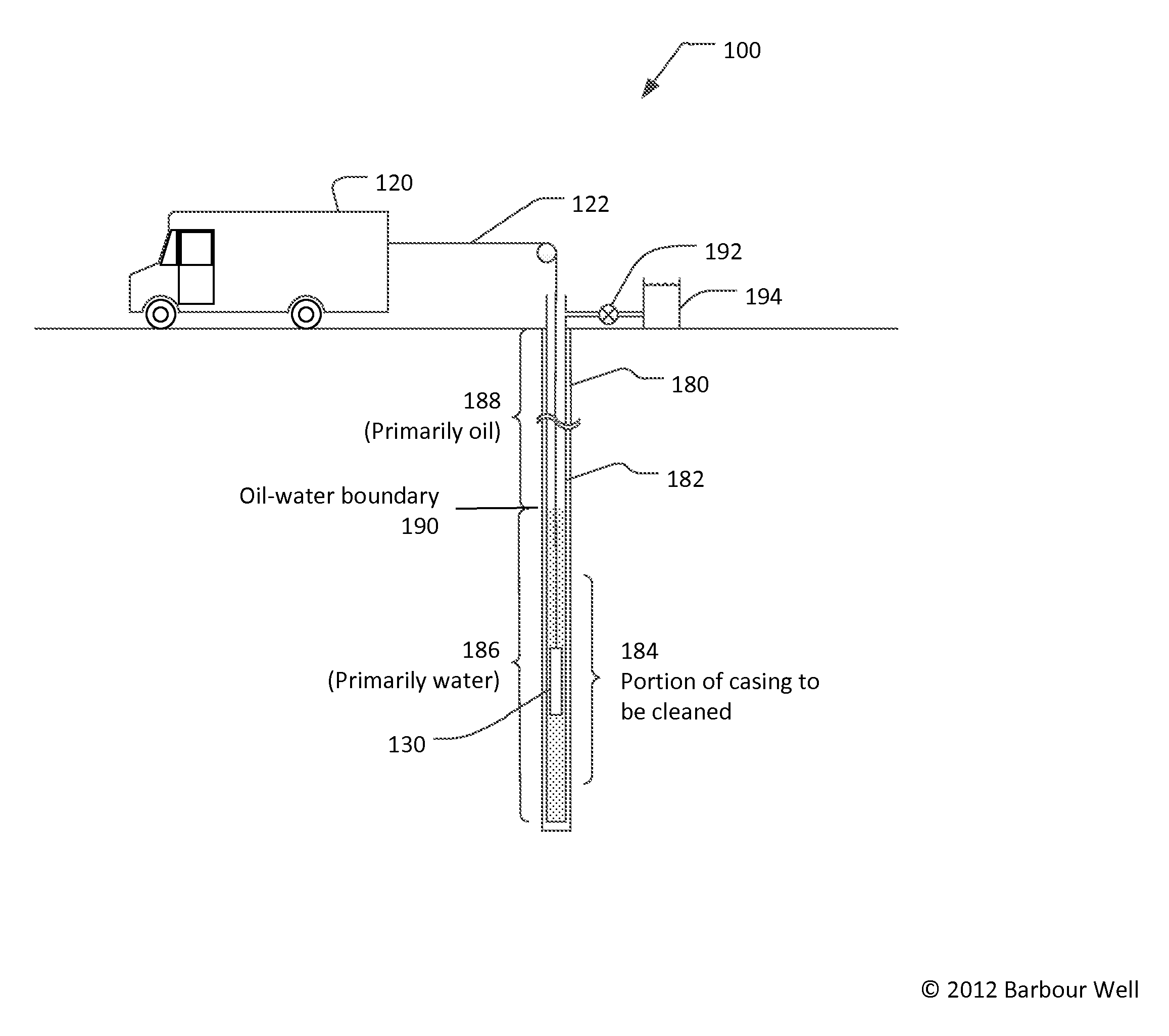
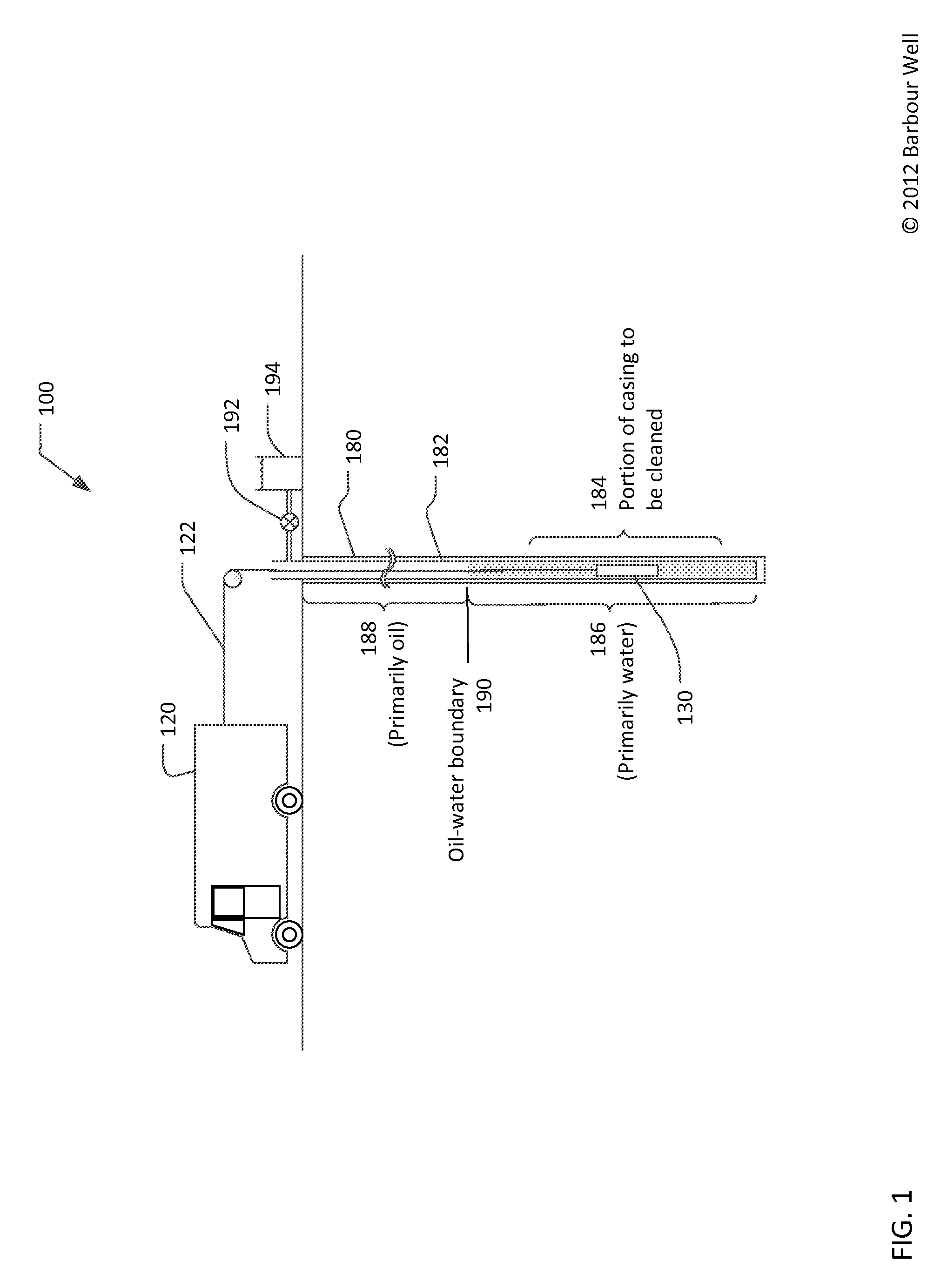
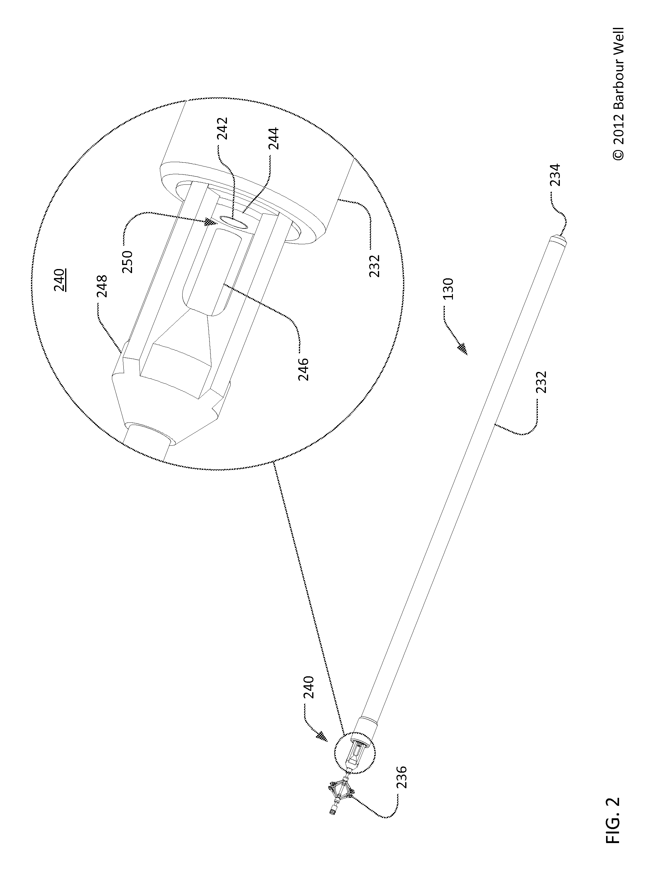
[0018]Referring now to FIG. 1, a well cleaning system 100 may include a surface installation 120 (illustrated in FIG. 1 as a truck), a cable 122, and a cleaning tool 130. The surface installation 120 may use the cable 122 to lower the cleaning tool 130 into a borehole 180 which is typically lined with a casing 182. All or portions of the annular space between the borehole 180 and the casing 182 may be filled with cement and / or gravel (not shown in FIG. 1). The cleaning tool 130 may be configured to create an electrical discharge between a pair of electrodes. The electrical discharge may, in turn, generate a shock wave in the fluid within the casing 182 to clean a portion of the casing proximate to the discharge location. The electrical discharge may also produce ozone and / or ultraviolet light which may provide an additive cleaning effect. The cleaning tool 130 may create electrical discharges at intervals as the tool is lowered into and / or withdrawn from the ...


PUM


Abstract

A method for cleaning a casing of an oil well is disclosed. Operational parameters for a cleaning tool may be defined based, at least in part, on results of a survey of the well. The cleaning tool may include a discharge head to generate electrical discharges between a pair of electrodes, the electrical discharges causing shock waves to remove deposits from the casing. The cleaning tool may be lowered into the casing. The cleaning tool may generate shock waves in accordance with the defined operational parameters to clean a predetermined target portion of the casing. The cleaning tool may be withdrawn from the casing.

Description

NOTICE OF COPYRIGHTS AND TRADE DRESS[0001]A portion of the disclosure of this patent document contains material which is subject to copyright protection. This patent document may show and / or describe matter which is or may become trade dress of the owner. The copyright and trade dress owner has no objection to the facsimile reproduction by anyone of the patent disclosure as it appears in the Patent and Trademark Office patent files or records, but otherwise reserves all copyright and trade dress rights whatsoever.RELATED APPLICATION INFORMATION[0002]This application is related to Patent Application No. xx / xxx,xxx, entitled WELL CLEANING TOOL, filed on the same date as this application.BACKGROUND[0003]1. Field[0004]This disclosure relates to a method of cleaning well bores, and in particular cleaning casings of oil wells, geothermal energy wells, and other wells.[0005]2. Description of the Related Art[0006]Petroleum products such as oil and natural gas are commonly produced by drilli...

Claims


Application Information

Patent Timeline
Patent Type & Authority Applications(United States)
IPC IPC(8): E21B37/00
CPCE21B37/00E21B28/00
Inventor BARBOUR, JOEL SCOTTCHAPMAN, DENNIS ANDREWWEATHERFORD, PAUL EDWARDMCCARTNEY, DAVID ANDREW
Owner PAST
Why Eureka
Try Eureka