Ion generation method and ion source
a technology of ion source and generation method, which is applied in the direction of solid cathode, gas-filled discharge tube, ion beam tube, etc., can solve problems such as contamination of wafers
- Summary
- Abstract
- Description
- Claims
- Application Information
AI Technical Summary
Benefits of technology
Problems solved by technology
Method used
Image
Examples
first embodiment
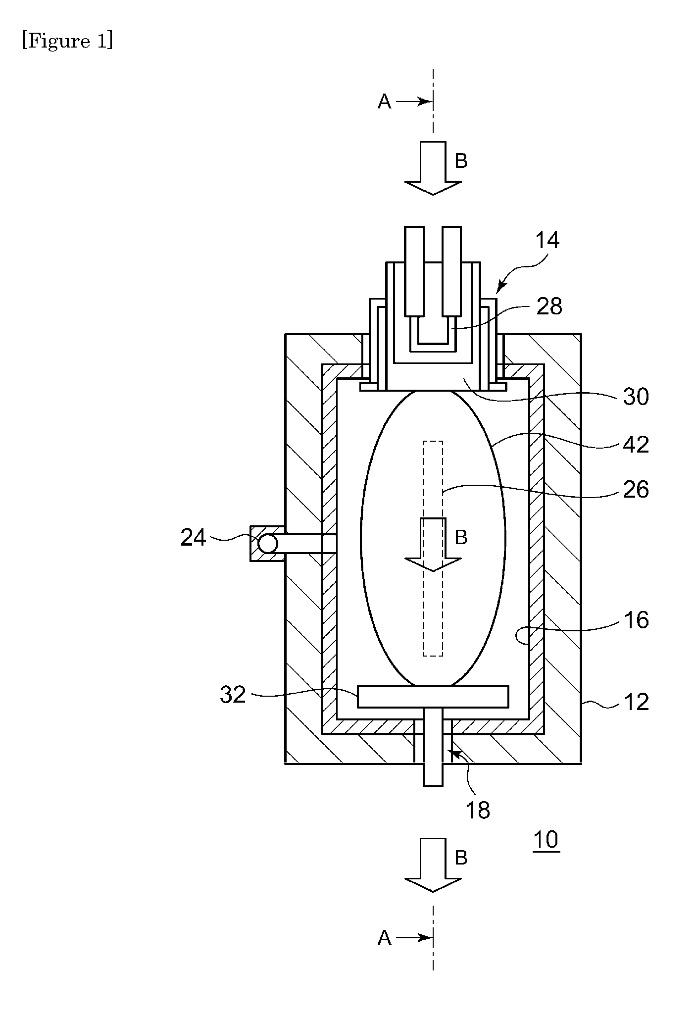
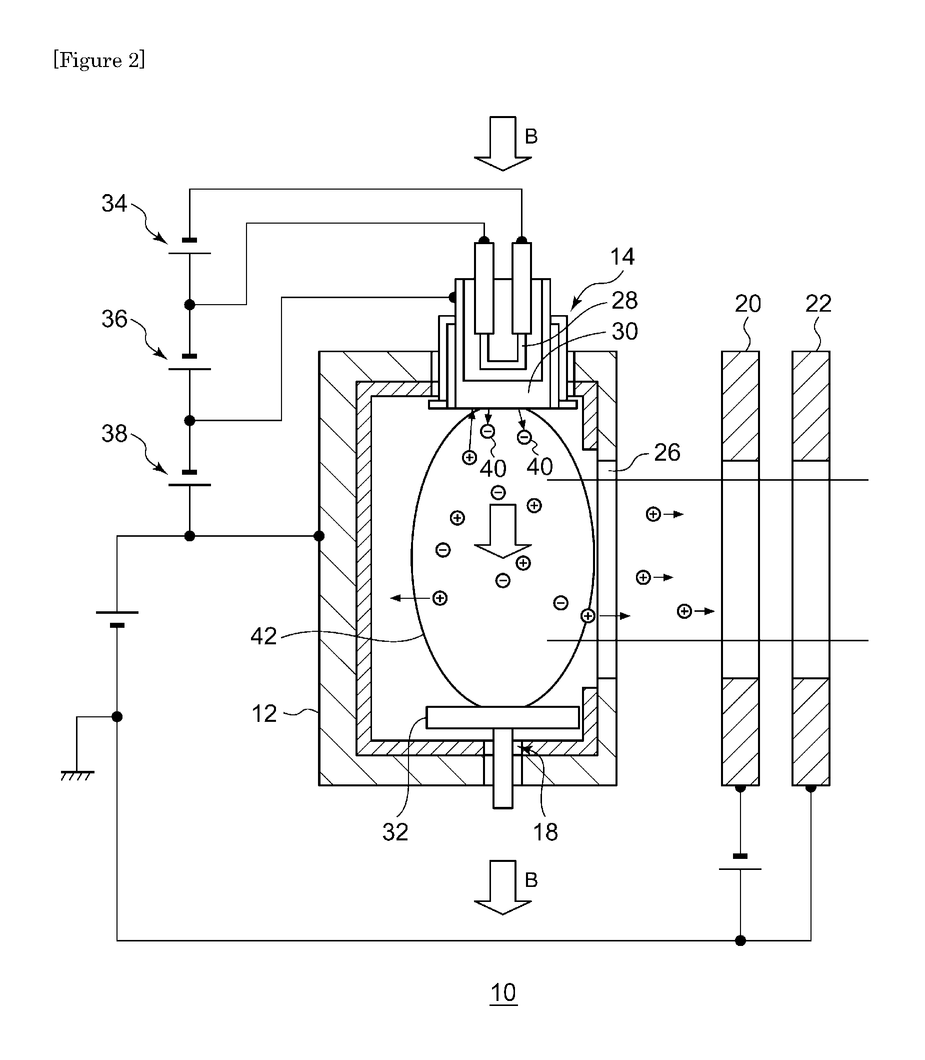
[0023]FIG. 1 is a schematic diagram showing the interior of the arc chamber of an ion source according to the first embodiment. FIG. 2 is a schematic diagram showing the A-A cross section of the ion source shown in FIG. 1.
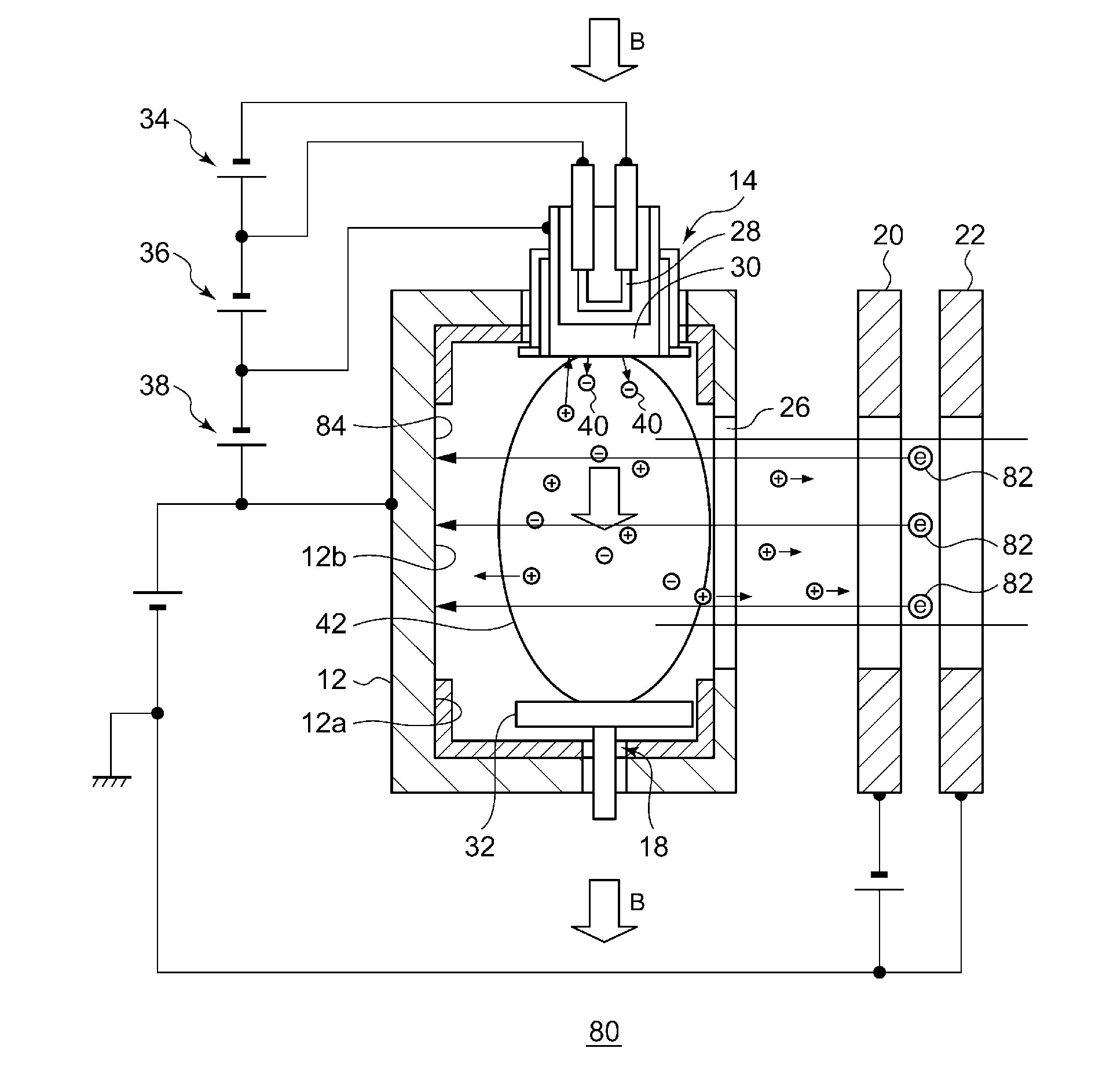
[0024]The ion source 10 according to the first embodiment is a DC discharge ion source and comprises an arc chamber 12, a thermoelectronic emission unit 14, a liner 16, a repeller 18, a suppression electrode 20, a ground electrode 22, and various power supplies.
[0025]The arc chamber 12 is formed with a gas introduction port 24 for introducing a source gas and a front slit 26 provided as an opening through which an ion beam is extracted.
[0026]The thermoelectronic emission unit 14 emits thermoelectrons in the arc chamber and includes a filament 28 and a cathode 30. The repeller 18 is provided to face the thermoelectronic emission unit 14 and includes a repeller plate 32. The cathode 30 and the repeller plate 32 are provided to face each other so as to be substantiall...
second embodiment
[0051]FIG. 3 is a schematic diagram showing the interior of the arc chamber of the ion source according to the second embodiment. An ion source 50 according to the second embodiment is different from the ion source 10 according to the first embodiment in respect of the shape of the liner.
[0052]The arc chamber 12 in the ion source 50 includes a liner-lined area 12a covered by a liner 52 in the neighborhood of the thermoelectronic emission unit 14, and an exposed area 12b not covered by the liner 52. Radicals are likely to be generated in the neighborhood of the thermoelectronic emission unit 14 so that radicals can be efficiently removed by locating the liner 52 in the neighborhood of the thermoelectronic emission unit 14. Meanwhile, by providing the exposed area 12b not covered by the liner, the amount of the liner 52 can be reduced so that the material forming the liner 52 is prevented from being turned into an ion beam in an excessive amount.
third embodiment
[0053]FIG. 4 is a schematic diagram showing the interior of the arc chamber of the ion source according to the third embodiment. An ion source 60 according to the third embodiment is different from the ion source 10 according to the first embodiment in respect of the shape of the liner.
[0054]The arc chamber 12 in the ion source 60 is provided with a liner-lined area 12a covered by a liner 62 in the neighborhood of the repeller 18 opposite to the thermoelectronic emission unit 14, and an exposed area 12b not covered by the liner 62. Radicals are likely to be generated in the neighborhood of the repeller 18 so that radicals can be efficiently removed by locating the liner 62 in the neighborhood of the repeller 18. Meanwhile, by providing the exposed area 12b not covered by the liner 62, the amount of the liner 62 can be reduced so that the material forming the liner 62 is prevented from being turned into an ion beam in an excessive amount.
PUM
 Abstract
Description
Claims
Application Information
 - R&D
- Intellectual Property
- Life Sciences
- Materials
- Tech Scout
- Unparalleled Data Quality
- Higher Quality Content
- 60% Fewer Hallucinations
Browse by: Latest US Patents, China's latest patents, Technical Efficacy Thesaurus, Application Domain, Technology Topic, Popular Technical Reports.
© 2025 PatSnap. All rights reserved.Legal|Privacy policy|Modern Slavery Act Transparency Statement|Sitemap|About US| Contact US: help@patsnap.com


