Motor driving device and method of controlling the same

Inactive Publication Date: 2014-03-06
SAMSUNG ELECTRO MECHANICS CO LTD
View PDF1 Cites 5 Cited by
  • Summary
  • Abstract
  • Description
  • Claims
  • Application Information

AI Technical Summary

Benefits of technology

[0010]An aspect of the present invention provides a motor driving device driven with low power at a low current by constantly operating some of a plurality of unit circuits included in a con

Problems solved by technology

In the case of motor driving, since all circuits are constantly operated, a c

Method used


Image

  • Motor driving device and method of controlling the same
  • Motor driving device and method of controlling the same
  • Motor driving device and method of controlling the same

Examples


Example

[0027]Embodiments of the present invention will be described in detail with reference to the accompanying drawings. The invention may, however, be embodied in many different forms and should not be construed as being limited to the embodiments set forth herein. Rather, these embodiments are provided so that this disclosure will be thorough and complete, and will fully convey the scope of the invention to those skilled in the art.

[0028]Hereinafter, a motor driving device and a method of controlling the same according to an embodiment of the present invention will be described. In particular, a motor having a hall sensor will be described for convenience of explanation, but the present invention is not limited thereto. The present invention may be applied to a motor having an optical sensor other than a hall sensor, a sensorless motor operated by a counter electromotive force (Back emf) signal.

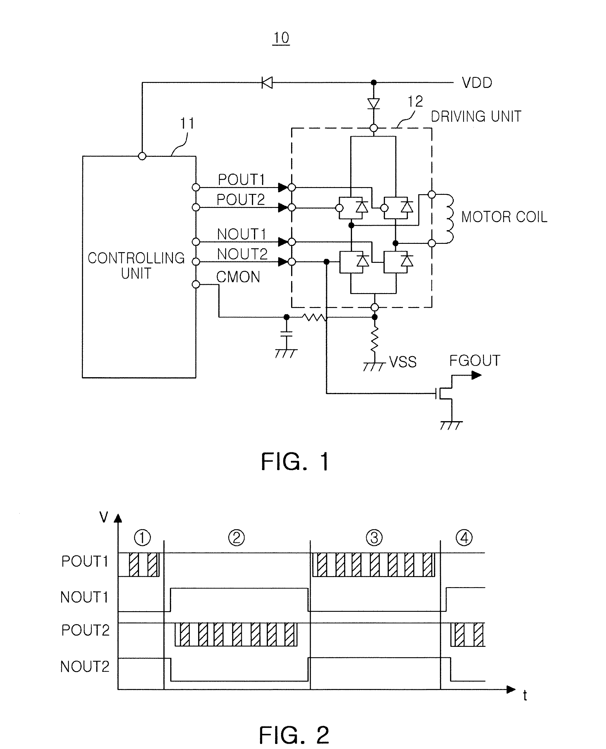
[0029]FIG. 1 is a view illustrating a configuration of a general motor driving device.

[0030]...


PUM


Abstract

There are provided a motor driving device and a method of controlling the same. The motor driving device includes a controlling unit; a plurality of unit circuits provided within the controlling unit and controlling driving of a motor; and a time slice controller provided within the controlling unit and periodically generating a wake-up signal, wherein some unit circuits among the plurality of unit circuits are operated for a certain operation time upon receiving the wake-up signal, thereby allowing for effective power consumption of the motor.

Description

CROSS-REFERENCE TO RELATED APPLICATIONS[0001]This application claims the priority of Korean Patent Application No. 10-2012-0098447 filed on Sep. 5, 2012, in the Korean Intellectual Property Office, the disclosure of which is incorporated herein by reference.BACKGROUND OF THE INVENTION[0002]1. Field of the Invention[0003]The present invention relates to a motor driving device and a method of controlling the same.[0004]2. Description of the Related Art[0005]Recently, electric devices or electronic devices have been increasingly used domestically, commercially and industrially due to high demand therefore. Such devices may employ a driving circuit for driving a particular operation. For example, a motor may be used therein.[0006]In general, a brushless direct contact (BLDC) motor refers to a DC motor having a function of applying a current or adjusting a current direction by using a contactless position detector and a semiconductor device without using a mechanical contact unit such as...

Claims


Application Information

Patent Timeline
IPC IPC(8): H02P6/06H02P29/00H02P6/08H02P6/16H02P6/17H02P6/26
CPCH02P6/06H02P6/085H02P2209/09Y10S388/901Y10S388/9072Y10S388/912
Inventor KO, JOO YUL
Owner SAMSUNG ELECTRO MECHANICS CO LTD
Why Eureka
Try Eureka