Method of near-field electromagnetic ranging and location

Active Publication Date: 2014-03-06
GAN CORP
View PDF0 Cites 30 Cited by
  • Summary
  • Abstract
  • Description
  • Claims
  • Application Information

AI Technical Summary

Problems solved by technology

This complex environment is known to effectively scramble or even block the propagation of radio frequency signals, especially those in the VHF, UHF and microwave part of the radio spectrum.
Rapid variations in amplitude and phase may occur as these signals scatter and interfere with one another in complex ways.
Difficulties with multi-path radio signal re

Method used


Image

  • Method of near-field electromagnetic ranging and location
  • Method of near-field electromagnetic ranging and location
  • Method of near-field electromagnetic ranging and location

Examples


Embodiment Construction

Overview of the Invention

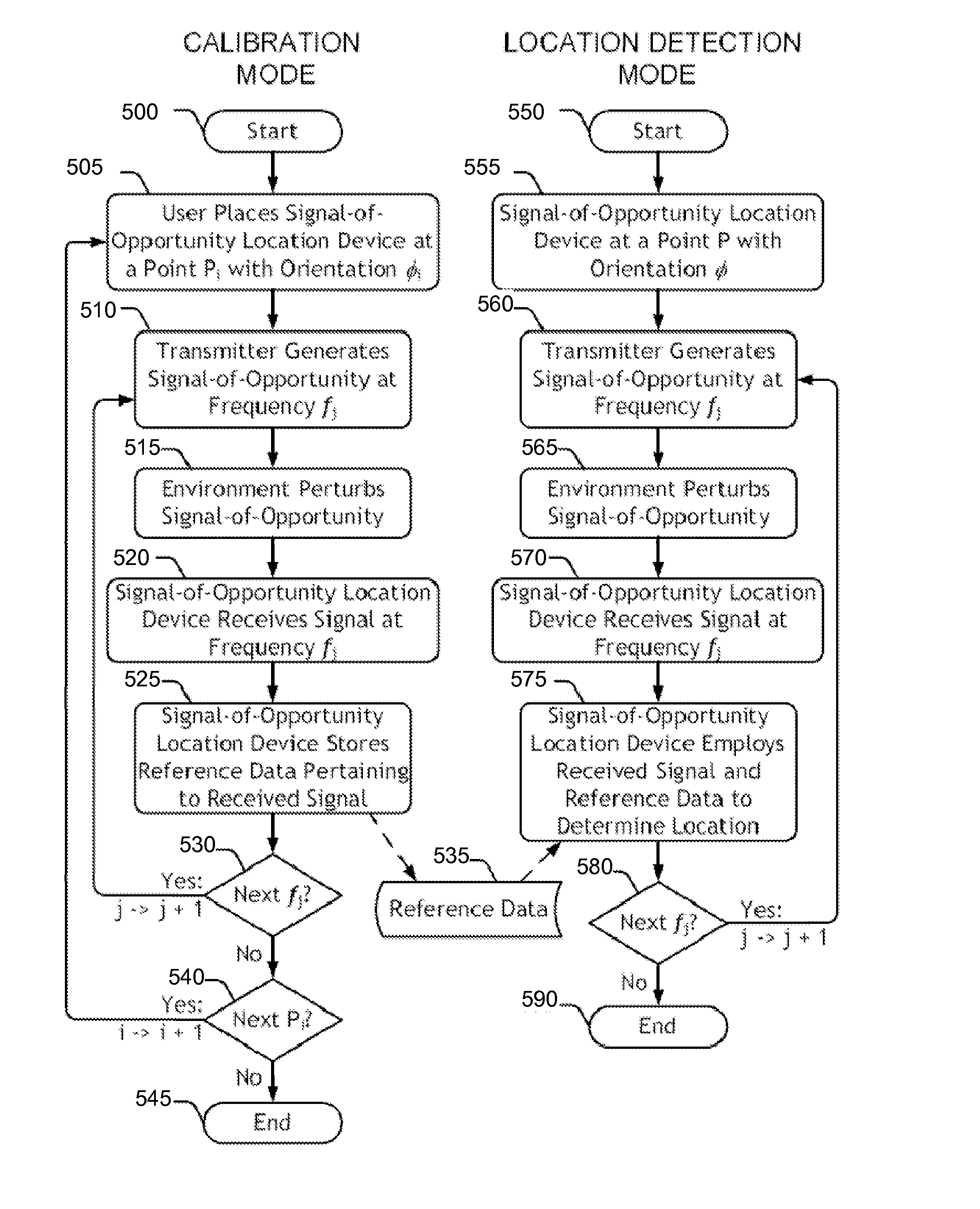
[0029]Real-time location system (RTLS) devices track an object's movement and measure the object's location to sufficient accuracy to identify the position of the object within the correct bin or region in the storage area or elsewhere. An important sub-set of RTLS use active wireless devices. Active RTLS may employ 2.4 GHz signals (for instance, Wi-Fi®, Bluetooth®, or ZigBee®), optical, IR, or laser signals, acoustic signals, ultra-wideband (UWB) signals, near-field signals, or other wireless signals. Active RTLS methods may include time-of-flight, time-difference-of-arrival, Received Signal Strength Indicator (RSSI), multilateration, line-of-sight, direction finding, radar, RF fingerprinting, or other methods.

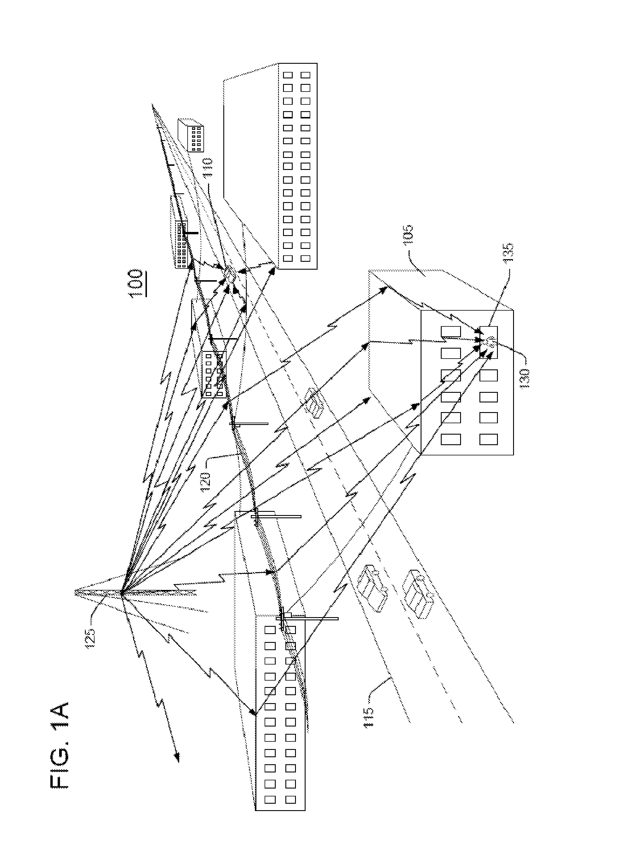
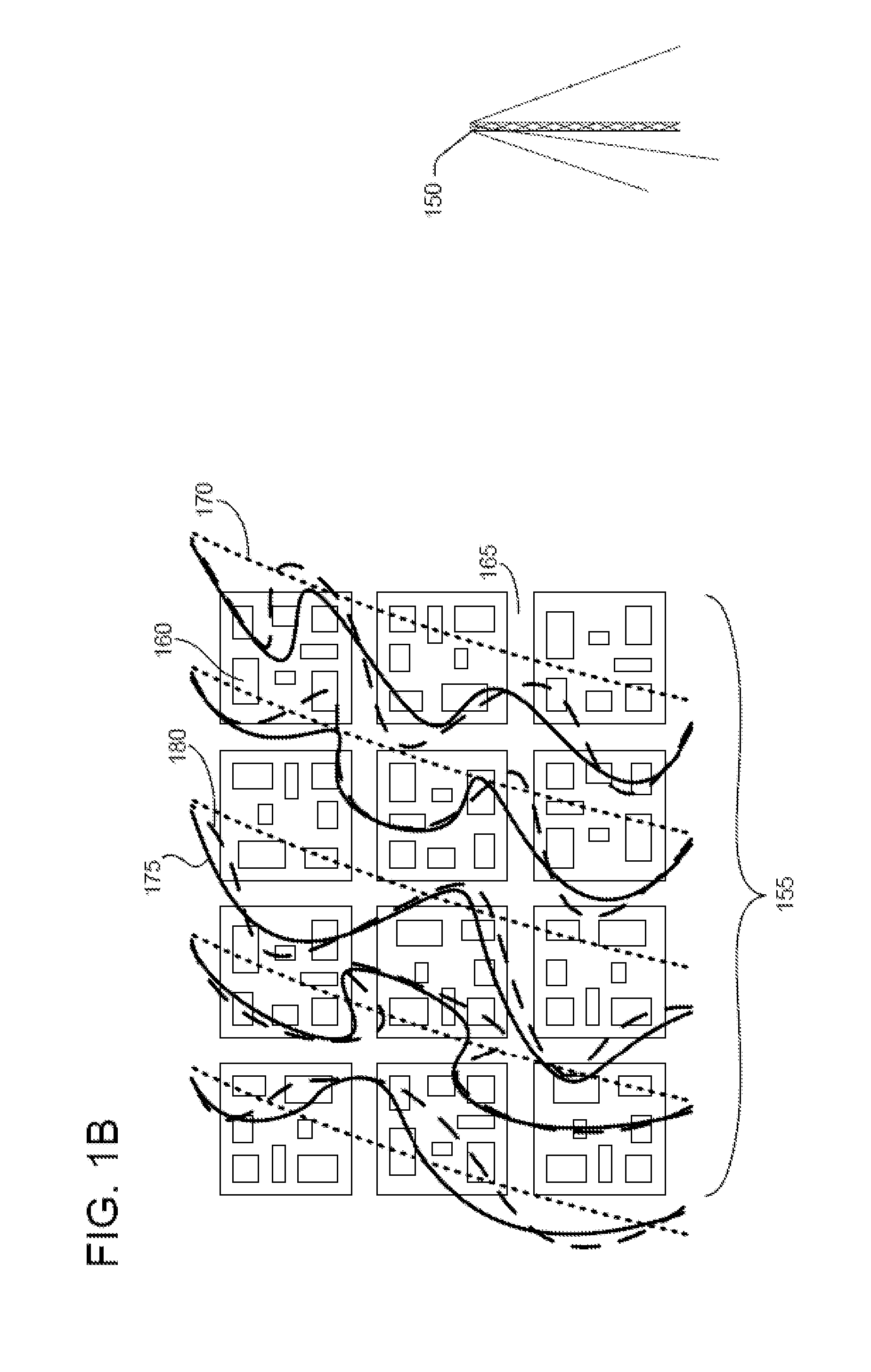
[0030]Incumbent location providers take high frequency, short wavelength wireless systems, like Wi-Fi or UWB, that were optimized for high data rate communications, and they try to use them to solve the challenging problem of indoor wireless location....


PUM


Abstract

A method of near-field electromagnetic ranging and location exploits the long-wavelength, near-field characteristics of low-frequency RF signals like those in the vicinity of the AM broadcast band. These signals are robust against scattering from small objects and only mildly perturbed by the urban landscape including building structures. They are thus amenable to an RF fingerprinting approach exploiting a coarse calibration to capture the behavior of the gradually varying signal characteristics. In embodiments, a method of near-field electromagnetic ranging and location may exploit transmit tags transmitting to an infrastructure of locator-receivers, or locator-receiver tags detecting signals from an infrastructure of fixed transmitter beacons. In still further embodiments, fixed transmitter beacons may be supplemented by uncooperative signals sources including signals-of-opportunity like AM broadcast band signals.

Description

RELATED APPLICATIONS[0001]The present application is a continuation-in-part of U.S. patent application Ser. No. 13 / 153,640 titled: “Inventory control system and method,” filed Jun. 6, 2011, now U.S. Pat. No. 8,326,451 issued Dec. 4, 2012 and its antecedents. The present application is a continuation-in-part of U.S. patent application Ser. No. 12 / 977,067 titled: “Near-field electromagnetic location system and method,” filed Dec. 23, 2010 and its antecedents. The present application is a continuation in part of U.S. patent application Ser. No. 12 / 834,821 titled: “Space efficient magnetic antenna method,” filed Jul. 12, 2010 and its antecedents. The present application is a continuation in part of U.S. patent application Ser. No. 12 / 857,528 titled: “Planar antenna system,” filed Aug. 16, 2010 and its antecedents. The present application is a continuation-in-part of U.S. patent application Ser. No. 13 / 436,956 titled: “Directive electrically small antenna system and method,” filed Apr. 1...

Claims


Application Information

Patent Timeline
IPC IPC(8): G01S5/02
CPCG01S5/02G01S13/751G01S13/878G06Q10/087G01S5/02525
Inventor SCHANTZ, HANS G.DEPIERRE, ROBERT E.UNDEN, ALFRED H.RICHARDS, ERIC ALEXANDER
Owner GAN CORP
Why Eureka
Try Eureka