
Electrophoretic display system

Active Publication Date: 2014-03-06
AU OPTRONICS CORP
View PDF20 Cites 3 Cited by
  • Summary
  • Abstract
  • Description
  • Claims
  • Application Information

AI Technical Summary

Benefits of technology

The invention is about a way to reduce the number of data lines between a timing controller and a data driver in an electrophoretic display system. This is done through multiple stages of serial-to-parallel conversion, which allows the timing controller to transmit data through a smaller number of lines. This reduces the overall circuit area and hardware costs of the display system. In simple terms, the invention allows for more efficient data transmission and reduces the size and cost of the display system.

Problems solved by technology

Thereby, the influence of traces undoubtedly lessens the likelihood of reducing the volume of the flexible display, such that the flexible display may not be able to satisfy the requirement for compactness and miniaturization.
Due to the demand for driving capability, the chip area of the data driver may be significant; namely, the hardware costs of the data driver may be considerable.

Method used


Image

  • Electrophoretic display system
  • Electrophoretic display system
  • Electrophoretic display system

Examples


Embodiment Construction

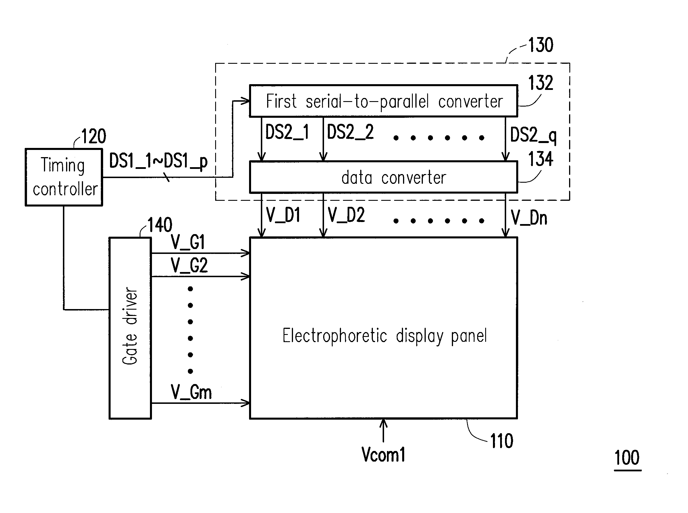
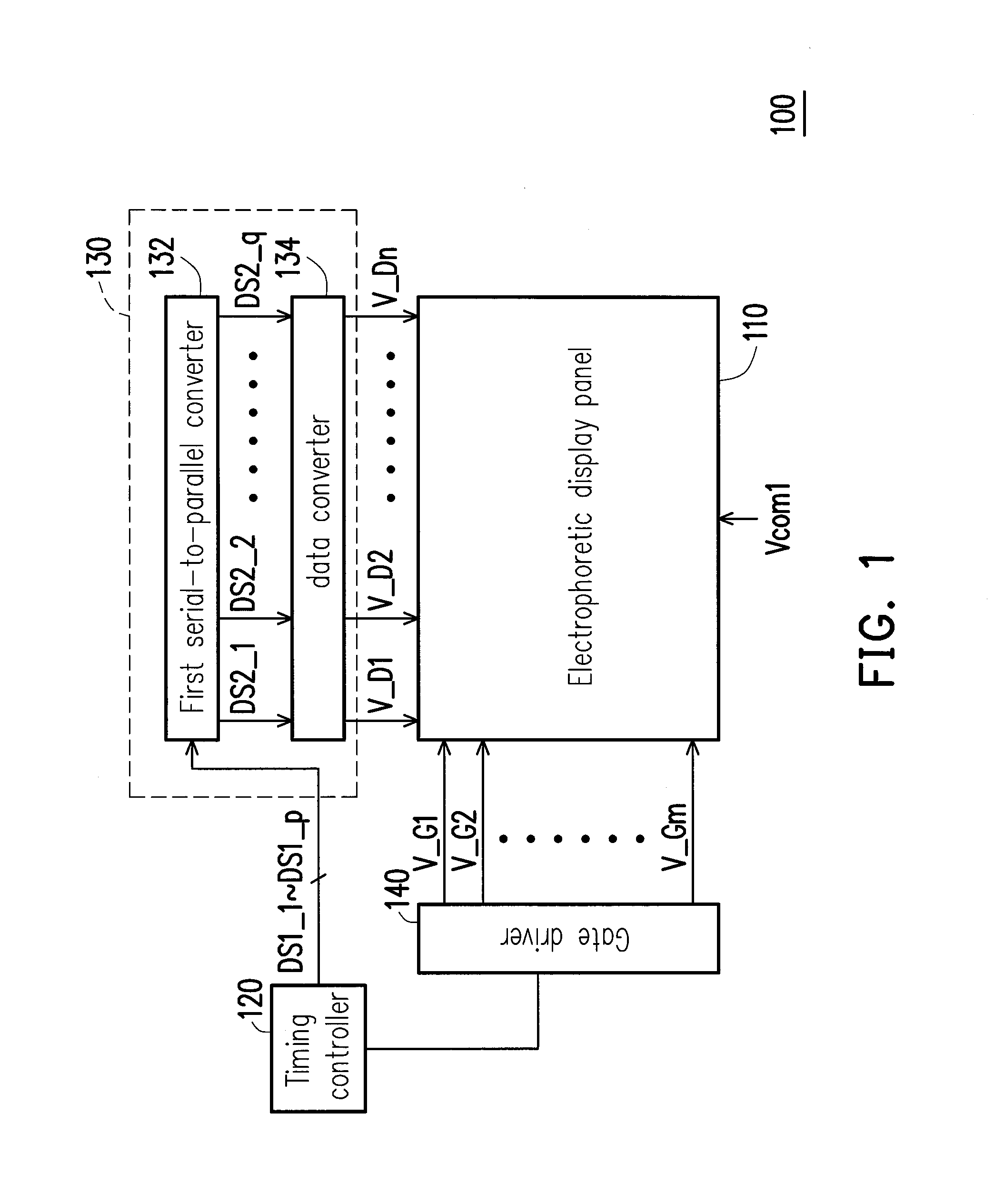
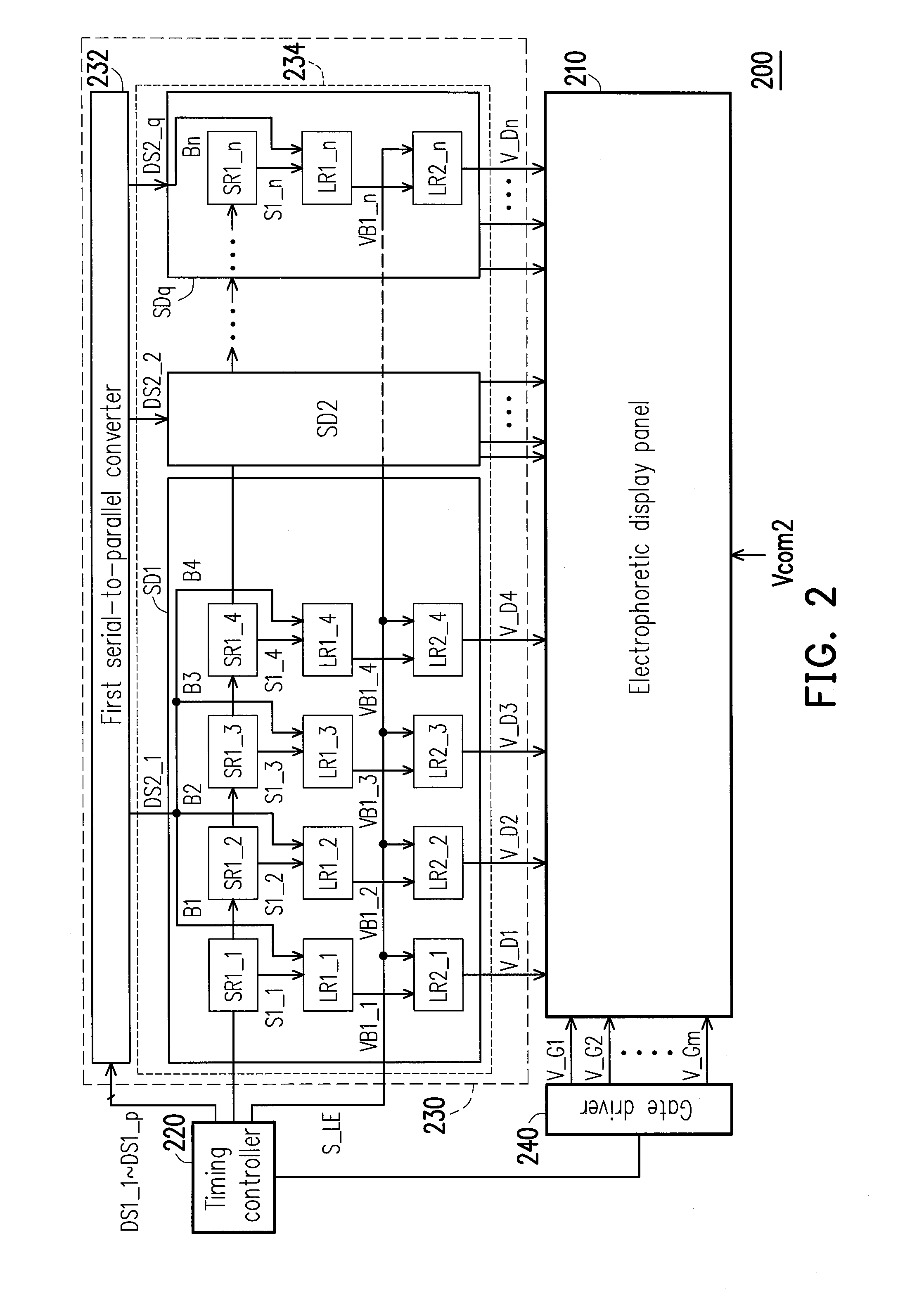
[0033]FIG. 1 is a schematic view illustrating an electrophoretic display system according to an embodiment of the invention. With reference to FIG. 1, an electrophoretic display system 100 described in the present embodiment includes an electrophoretic display panel 110, a timing controller 120, a data driver 130, and a gate driver 140. In the present embodiment, the data driver 130 receives first series data DS1_1˜DS1—p provided by the timing controller 120 and converts the first series data DS1_1˜DS113 into corresponding display voltages V_D1˜V_Dn to drive the electrophoretic display panel 110. The gate driver 140 is electrically connected to the electrophoretic display panel 110 and the timing controller 120 and controlled by the timing controller 120 to provide a plurality of gate driving voltages V_G1˜V_Gm to the electrophoretic display panel 110. The electrophoretic display panel 110 receives a common voltage Vcom1. Here, m, n, and p are positive integers, p is smaller than n,...


PUM


Abstract

An electrophoretic display system includes an electrophoretic display panel, a timing controller, a data driver, and a gate driver. The data driver includes a first serial-to-parallel converter and a data converter. The first serial-to-parallel converter receives a plurality of first series data and converts the first series data into a plurality of second series data. The quantity of the second series data is more than the quantity of the first series data. The data converter receives the second series data and is electrically connected to the electrophoretic display panel. Besides, the data converter converts the second series data into display voltages, and the quantity of the display voltages is more than the quantity of the second series data. The gate driver is electrically connected to the electrophoretic display panel and the timing controller and controlled by the timing controller to provide gate driving voltages to the electrophoretic display panel.

Description

CROSS-REFERENCE TO RELATED APPLICATION[0001]This application claims the priority benefit of Taiwan application serial no. 101131786, filed on Aug. 31, 2012. The entirety of the above-mentioned patent application is hereby incorporated by reference herein and made a part of this specification.BACKGROUND OF THE INVENTION[0002]1. Field of the Invention[0003]The invention relates to a display system, and in particular to an electrophoretic display system.[0004]2. Description of Related Art[0005]With the continual research on and the recent advancement of various display technologies, displays, such as electrophoretic displays (EPD), liquid crystal displays (LCD), plasma display panels (PDP), and organic light-emitting diode (OLED) displays, have been gradually commercialized and applied to devices in different sizes and with different areas. Besides, the popularity of portable electronic devices calls the attention of the market to flexible displays, e.g., e-paper, e-book, and so on.[00...

Claims


Application Information

Patent Timeline
IPC IPC(8): G09G3/20
CPCG09G3/20G09G3/344G09G2310/0275G09G2310/0286G09G2310/0289
Inventor KUO, PING-SHENGHWU, KEH-LONGCHAN, CHIH-CHENGLAN, YUNG-HSIANGYU, CHIH-YU
Owner AU OPTRONICS CORP
Learn More